Adhesive wire molding

a technology of adhesive wire and wire rod, applied in the field of adhesive wire molding, to achieve the effect of easy cutting to length

Inactive Publication Date: 2012-06-19
FULCO SUSAN
View PDF21 Cites 6 Cited by
  • Summary
  • Abstract
  • Description
  • Claims
  • Application Information

AI Technical Summary

Benefits of technology

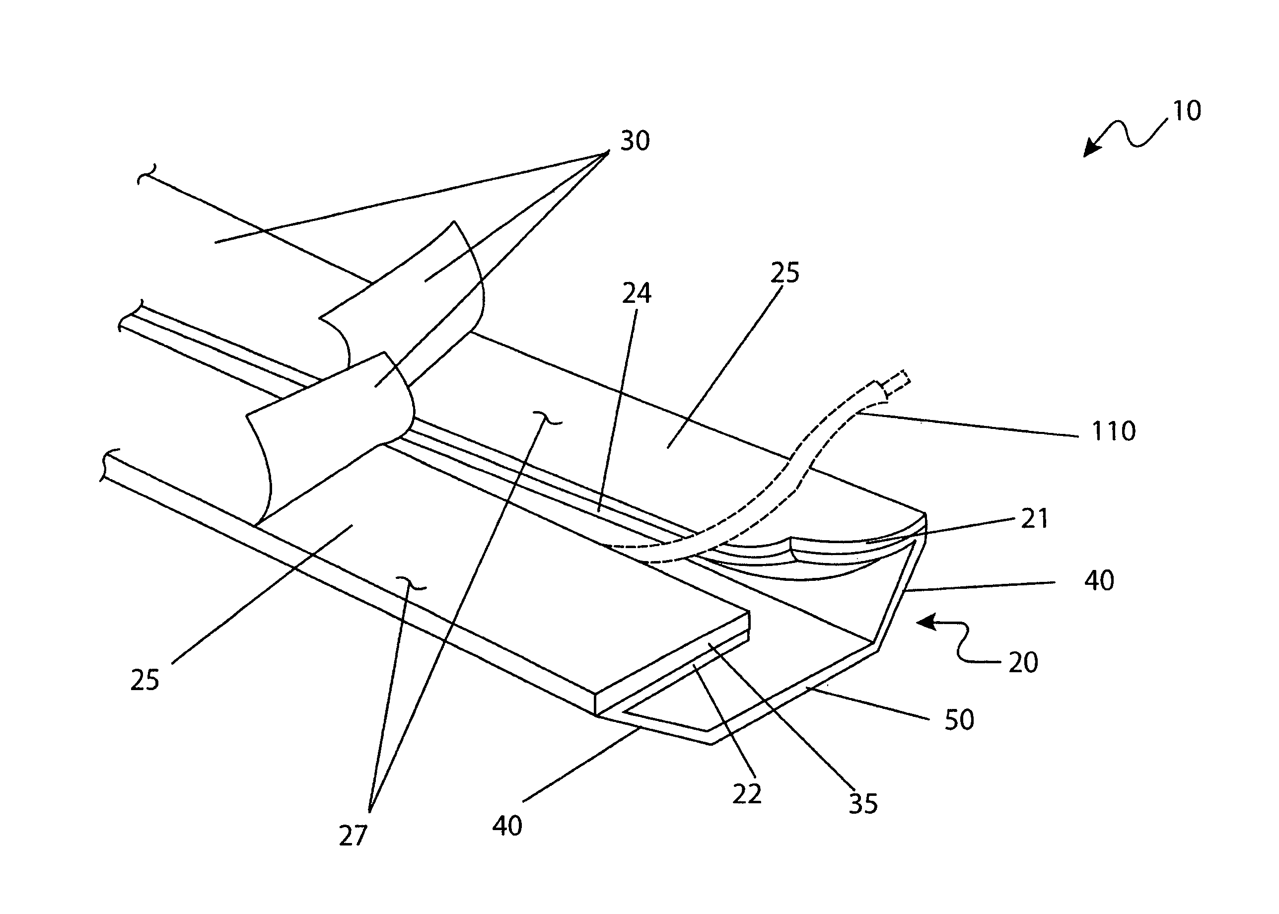
[0020]Still a further object of the adhesive wire molding device provides said device comprising a pre-split portion down a center region to aid in installation of wires and cables during initial installation.
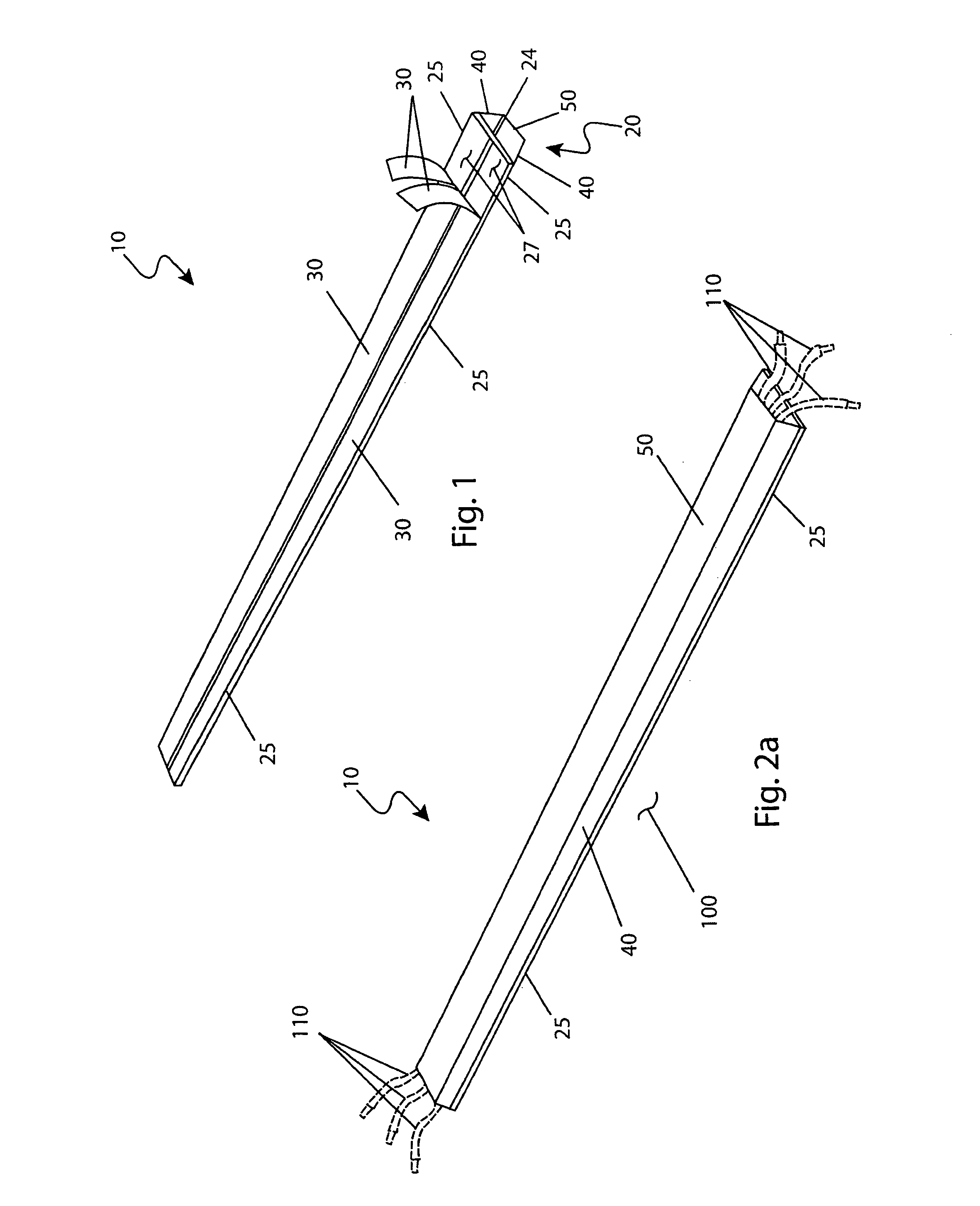
[0023]Another object of the adhesive wire molding device provides for said device to be length adjusted by being easily cut to length.

Problems solved by technology

In light of the disadvantages present in the prior art as previously described, it is apparent that there is a need for an adhesive wire molding device which provides a rubber or plastic split conduit with a self-adhesive backing used to route and organize an object or a plurality of objects along wall surfaces.

Method used


Image

  • Adhesive wire molding
  • Adhesive wire molding
  • Adhesive wire molding

Examples


Embodiment Construction

[0039]The best mode for carrying out the invention is presented in terms of its preferred embodiment, herein depicted within FIGS. 1 through 6. However, the invention is not limited to the described embodiment and a person skilled in the art will appreciate that many other embodiments of the invention are possible without deviating from the basic concept of the invention, and that any such work around will also fall under scope of this invention. It is envisioned that other styles and configurations of the present invention can be easily incorporated into the teachings of the present invention, and only one particular configuration shall be shown and described for purposes of clarity and disclosure and not by way of limitation of scope.

[0040]The terms “a” and “an” herein do not denote a limitation of quantity, but rather denote the presence of at least one of the referenced items.

[0041]The present invention describes an adhesive wire molding (herein described as the “device”) 10, wh...


PUM


Abstract

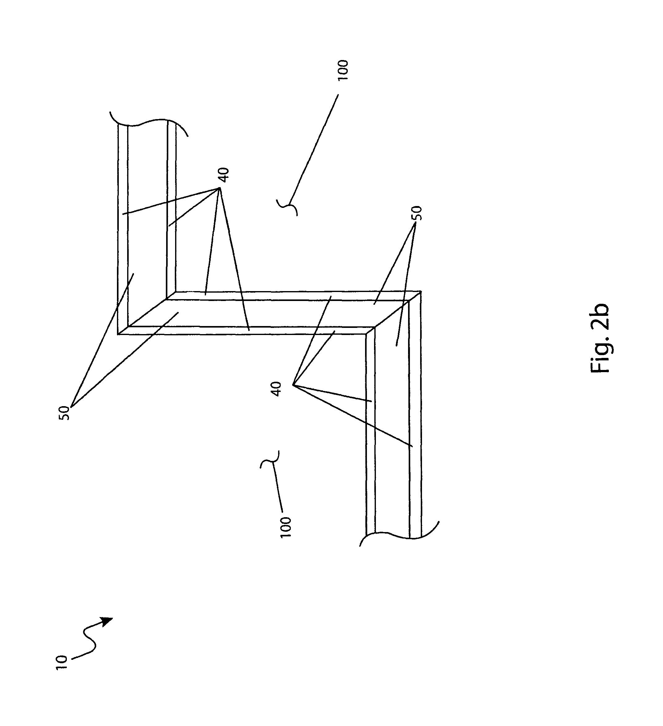
A conduit with a self-adhesive backing used to route and organize electrical or electronic cables along wall surfaces is herein disclosed. The conduit comprises a trapezoidal-shaped enclosure available in multiple widths from approximately two (2) inches up to six (6) inches. The smaller size would be used for one (1) or two (2) cables while the larger size conduit could be used with up to ten (10) cables. The rear or flat side of the conduit would be fastened to the wall surface using a pre-applied double-sided foam adhesive tape. The tape would be covered with a common release paper which would be peeled off just before application. The back section of the conduit would also be pre-split down the center to aid in the installation of wires and cable during initial installation. The conduit comprises a flexible material such as plastic or rubber to allow routing along irregular wall surfaces and can be cut to length with regular household scissors. It is envisioned the conduit may be introduced in multiple colors to match various decors and can also be painted to match existing wall surfaces.

Description

RELATED APPLICATIONS[0001]The present invention was first described in a notarized Official Record of Invention on Feb. 22, 2008, that is on file at the offices of Montgomery Patent and Design, LLC, the entire disclosures of which are incorporated herein by reference.FIELD OF THE INVENTION[0002]The present invention relates generally to a conduit with a self-adhesive backing used to route and organize electrical or electronic cables along a wall surface and, more particularly, to said conduit comprising a bottom side of the conduit capable of being fastened to the wall surface using a pre-applied double-sided foam adhesive tape, covered with a common release paper removable just prior to application, and a bottom side of the conduit is split down the center to aid in the installation of wires and cables therein the conduit.BACKGROUND OF THE INVENTION[0003]The proliferation of computers, home theatre systems, and other electronic devices in the home and office environment has blossom...

Claims


Application Information

Patent Timeline
Patent Type & Authority Patents(United States)
IPC IPC(8): H02G3/04
CPCH02G3/0431
Inventor FULCO, SUSAN
Owner FULCO SUSAN
Why Eureka
Try Eureka