Stabilizer and reamer system having extensible blades and bearing pads and method of using same

a technology of stabilizer and reamer, which is applied in the direction of drilling casings, drilling pipes, drilling rods, etc., can solve the problems of premature actuation, narrow boreholes, and small casings that have the disadvantage of narrowing boreholes,

Active Publication Date: 2012-06-26
BAKER HUGHES HLDG LLC
View PDF149 Cites 24 Cited by
  • Summary
  • Abstract
  • Description
  • Claims
  • Application Information

AI Technical Summary

Benefits of technology

[0012]Independent activation or triggering of the blades of an expandable reamer and the bearing pads of an expandable stabilizer as a system are provided. Independent activation of the reamer and stabilizer will provide a degree of control over the stabilizer, which is used to stabilize the reamer, without necessarily having to initiate both tools at the same time. For example, the reamer may be activated or triggered by a first actuation device to allow the pressure of fluid flowing through the reamer's body to extend the blades outward, without necessarily having to extend the bearing pads of the stabilizer, located longitudinally above the reamer, advantageously allowing the reamer to ream in the up-hole direction with the bearing pads of the stabilizer in their initial or retracted position without being forced upon or impinging (under the force of hydraulic fluid) against the walls of the to-be-reamed borehole. When downhole reaming is desired or the stabilizer blades are to be released (i.e., triggered) from their retracted or initial position, a second actuation device may be used to activate or trigger the stabilizer.
[0013]Optionally, the up-hole device may be a second expandable reamer allowing the downhole reamer to be actuated before the second reamer is actuated, released, or triggered. Embodiments of the invention may optionally be used with an expandable stabilizer during upward movement in a borehole, or for enabling a reamed or drilled borehole to be trimmed more efficiently in the up-hole direction while simultaneously providing reduced lateral vibration in the bottom-hole assembly, particularly when it is desired to extend, by triggering, the blades of the expandable stabilizer to their fullest extent for reaming in the down-hole direction.
[0014]The invention may be used with systems for drilling subterranean boreholes and, more particularly, to apparatus having consecutively initiated extensible blades and bearing pads, and methods of use thereof, for enlarging a subterranean borehole below a restriction, such as casing or liner. Furthermore, the invention relates to improved methods and apparatus for improving stabilization of a drilling assembly while under-reaming in either the down-hole or up-hole directions and controlling directional tendencies and reducing undesirable vibrational effects of the drilling assembly within an enlarged borehole. Optionally, the invention may be used with an expandable stabilizer provided with up-hole cutting structures upon the bearing pads of the expandable stabilizer for trimming a previously enlarged subterranean borehole, particularly when so-called “back-reaming” of the enlarged borehole is desired and when the bearing pads of an expandable stabilizer are subsequently expanded to the same lateral extent as the extensible blades of the expandable reamer.

Problems solved by technology

However, while adding additional casing allows a borehole to reach greater depths, the additional, smaller casing has the disadvantage of narrowing the borehole.
Moreover, the fluid-or pressure-operated expandable reamers and expandable stabilizers may overcome other limitations associated with conventional expandable reaming assemblies, such as being subject to damage when passing through a smaller diameter borehole or casing section, becoming prematurely actuated, and difficulties in removal through the casing after actuation.
For instance, conventional systems for stabilizing while reaming a borehole (especially while back-reaming a drilled borehole) may encounter subterranean formation changes within the formation of the drilled borehole (i.e., a tight spot of swelled shale or filter cake in the formation, or other obstructions) making retraction of the stabilizer and reamer necessary while trimming or back-reaming, this being undesirable in that an under-gage borehole results.

Method used


Image

  • Stabilizer and reamer system having extensible blades and bearing pads and method of using same
  • Stabilizer and reamer system having extensible blades and bearing pads and method of using same
  • Stabilizer and reamer system having extensible blades and bearing pads and method of using same

Examples


Embodiment Construction

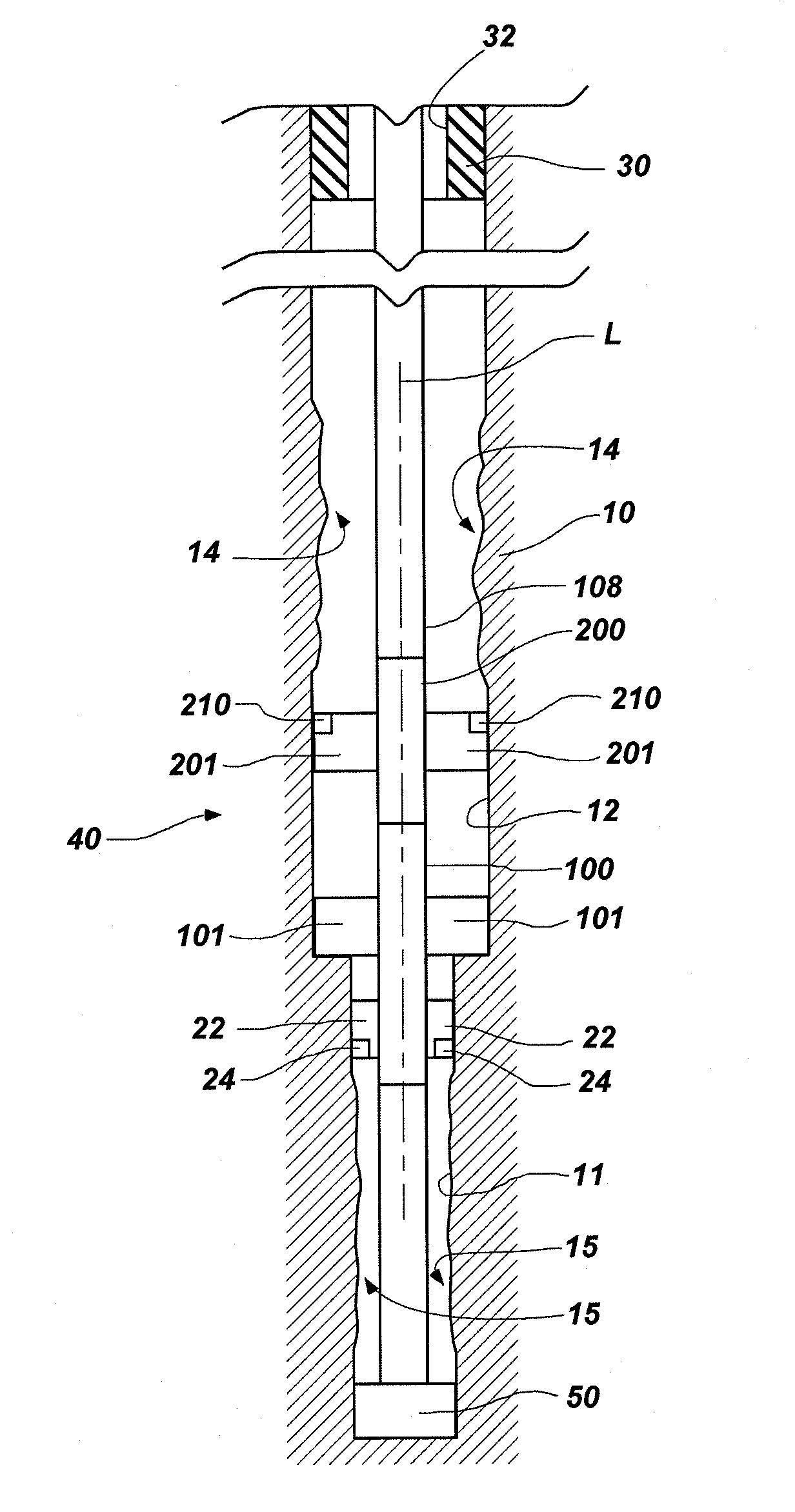
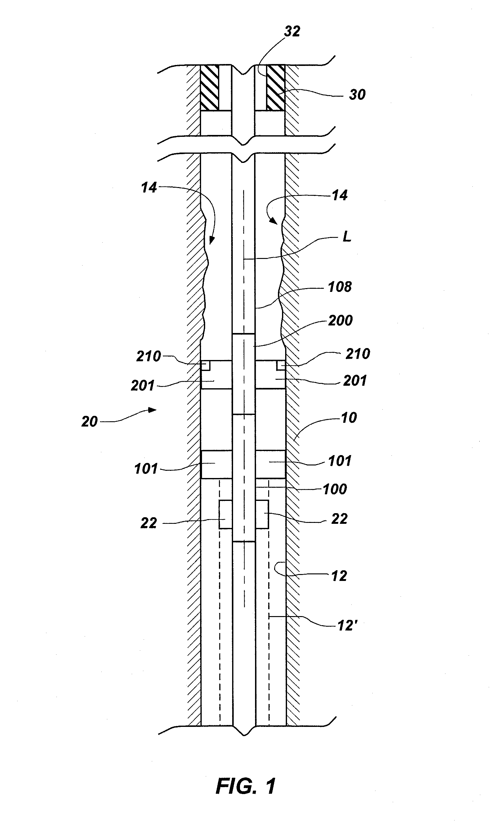
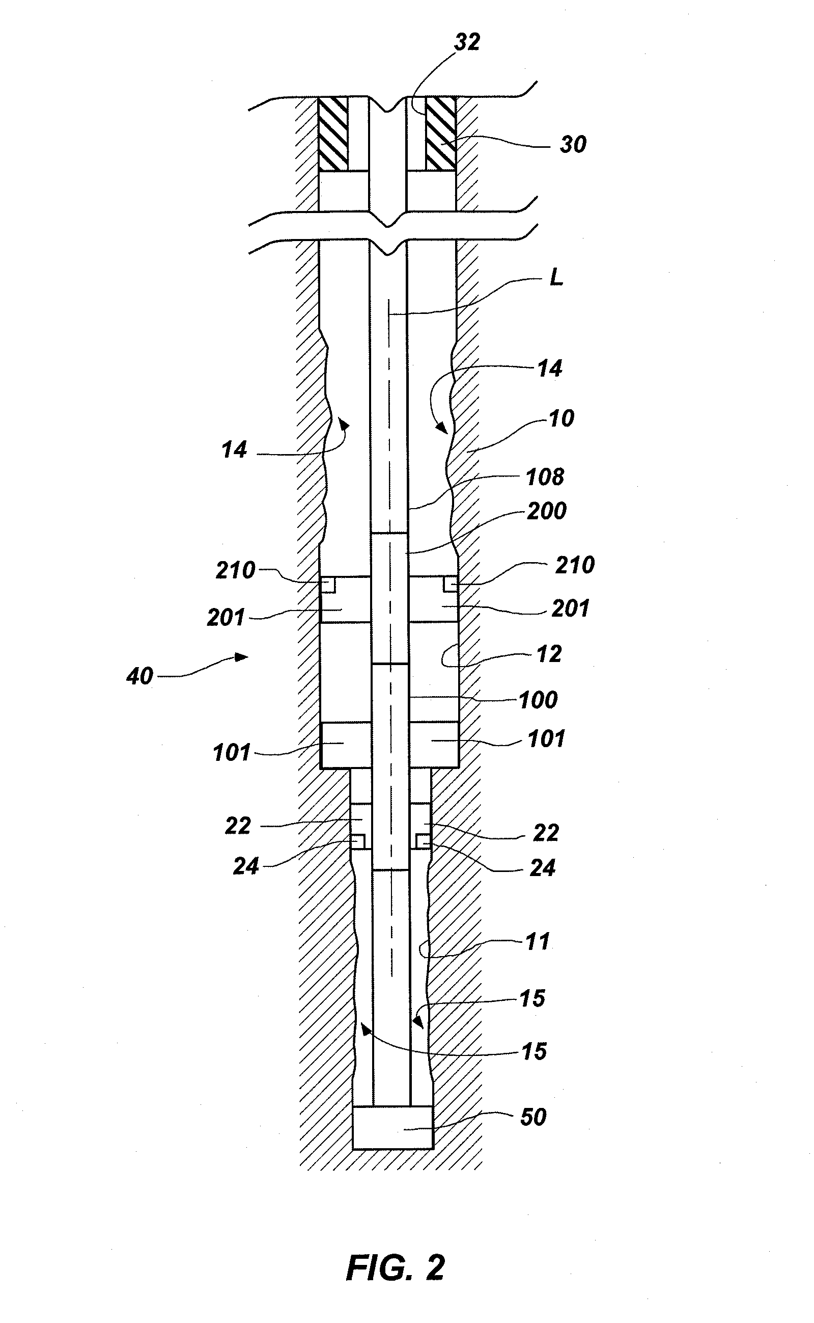
[0022]The illustrations presented herein are, in most instances, not actual views of any particular reamer tool, stabilizer tool, drill string, cutting element, or other feature of a stabilizer and reamer system of a drilling assembly, but are merely idealized schematic representations that are employed to describe the present invention. Additionally, elements common between figures may retain the same numerical designation. Moreover, the lateral and longitudinal dimensions shown in the figures are merely idealized representations, as the actual dimensions are expected to vary according to specific application requirements in the field.

[0023]FIG. 1 is a longitudinal schematic view of a drilling assembly in accordance with an embodiment of the invention. A section of a drilling assembly generally designated by reference numeral 20 is shown reaming a borehole 12 extending through a formation 10 with an expandable reamer 100 followed by an expandable stabilizer 200. The expandable ream...


PUM


Abstract

Drilling systems and methods for enlarging a borehole that include at least one expandable reamer and at least one expandable stabilizer axially spaced therefrom in a tubular string, such as a drill string, the at least one expandable reamer and the at least one expandable stabilizer being independently actuatable by different-sized actuation devices. A relatively lower tool is actuatable by a smaller actuation device, such as a drop ball, which passes through a relatively higher tool in the drill string without triggering the higher tool.

Description

CROSS-REFERENCE TO RELATED APPLICATIONS[0001]This application claims the benefit of U.S. provisional patent application Ser. No. 61 / 049,617, filed May 1, 2008. The subject matter of this application is related to U.S. patent application Ser. No. 13 / 038,564, filed Mar. 2, 2011, pending, which is a continuation of U.S. patent application Ser. No. 11 / 949,259, filed Dec. 3, 2007, now U.S. Pat. No. 7,900,717, issued Mar. 8, 2011; U.S. patent application Ser. No. 11 / 949,405, filed Dec. 3, 2007, pending; U.S. patent application Ser. No. 12 / 058,384, filed Mar. 28, 2008, now U.S. Pat. No. 7,882,905, issued Feb. 8, 2011; U.S. patent application Ser. No. 12 / 715,610, filed Mar. 2, 2010, pending; and U.S. patent application Ser. No. 12 / 501,688, filed Jul. 13, 2009, pending.TECHNICAL FIELD[0002]Embodiments of the present invention relate generally to a system for drilling a subterranean borehole and, more particularly, to a system having at least two independently actuatable downhole assemblies, ...

Claims


Application Information

Patent Timeline
Patent Type & Authority Patents(United States)
IPC IPC(8): E21B10/32
CPCE21B10/322E21B17/1078
Inventor RADFORD, STEVEN R.
Owner BAKER HUGHES HLDG LLC
Why Eureka
Try Eureka