Stabilizer and reamer system having extensible blades and bearing pads and method of using same

a technology of stabilizer and reamer, which is applied in the direction of earth drilling and mining, drill bits, drilling machines and methods, etc., can solve the problems of premature actuation, narrow borehole, and difficulty in removal through the casing, so as to prevent sticking of an expandable stabilizer, reduce lateral vibration, and reduce the effect of trimmed efficiency

Active Publication Date: 2009-10-01
BAKER HUGHES INC
View PDF100 Cites 15 Cited by
  • Summary
  • Abstract
  • Description
  • Claims
  • Application Information

AI Technical Summary

Benefits of technology

[0011]In order to prevent sticking of an expandable stabilizer during upward movement in a borehole, or for enabling a reamed or drilled borehole to be trimmed more efficiently in the up-hole direction while simultaneously providing reduced lateral vibration in the bottom hole assembly, drilling systems and methods for enlarging a borehole are provided.

Problems solved by technology

However, while adding additional casing allows a borehole to reach greater depths, the additional, smaller casing has the disadvantage of narrowing the borehole.
Moreover, the fluid or pressure operated expandable reamers and expandable stabilizers may overcome other limitations associated with conventional expandable reaming assemblies, such as being subject to damage when passing through a smaller diameter borehole or casing section, becoming prematurely actuated, and difficulties in removal through the casing after actuation.
For instance, conventional systems for stabilizing while reaming a borehole (especially while back reaming a drilled borehole) may encounter subterranean formation changes within the formation of the drilled borehole (i.e., a tight spot of swelled shale or filter cake in the formation, or other obstructions) making retraction of the stabilizer and reamer necessary, while trimming or back reaming, this being undesirable in that an under-gage borehole results.

Method used


Image

  • Stabilizer and reamer system having extensible blades and bearing pads and method of using same
  • Stabilizer and reamer system having extensible blades and bearing pads and method of using same
  • Stabilizer and reamer system having extensible blades and bearing pads and method of using same

Examples


Embodiment Construction

[0025]The illustrations presented herein are, in most instances, not actual views of any particular reamer tool, stabilize tool, drill string, cutting element, or other feature of a stabilizer and reamer system of a drilling assembly, but are merely idealized schematic representations that are employed to describe the present invention. Additionally, elements common between figures may retain the same numerical designation. Moreover, the lateral and longitudinal dimensions shown in the figures are merely idealized representation, as the actual dimensions are expected to vary according to specific application requirements in the field.

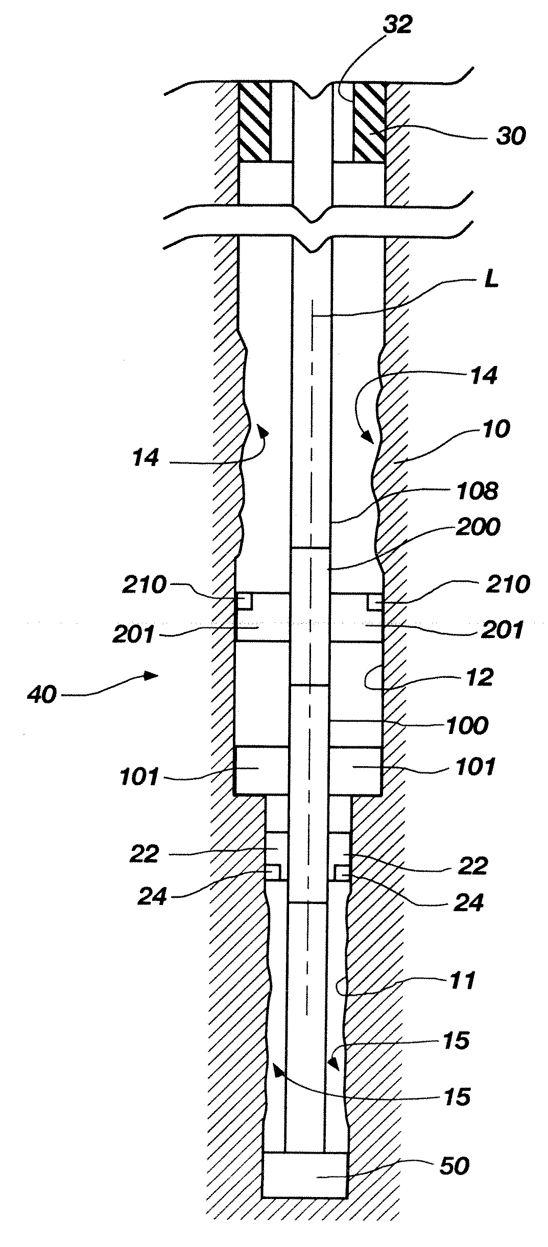
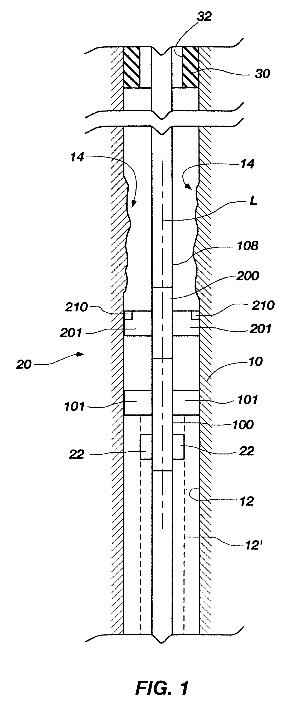
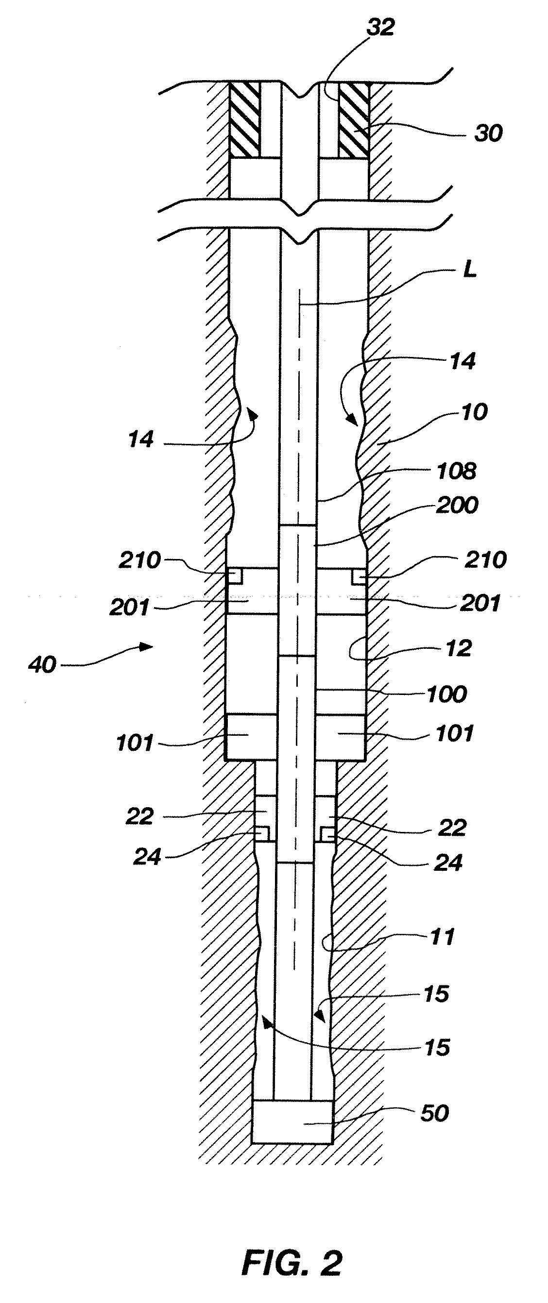
[0026]FIG. 1 is a longitudinal schematic view of a drilling assembly in accordance with an embodiment of the invention. A section of a drilling assembly generally designated by reference numeral 20 is shown reaming a borehole 12 extending through a formation 10 with an expandable reamer 100 followed by an expandable stabilizer 200. The expandable reamer...


PUM


Abstract

Drilling systems and methods for enlarging a borehole that include an expandable reamer and an expandable stabilizer axially coupled above the expandable reamer. The expandable reamer includes a tubular body having a longitudinal axis and a drilling fluid flow path therethrough, a plurality of generally radially and longitudinally extending blades carried by the tubular body, and a cutting structure carried by at least one blade of the plurality of blades, wherein at least one blade of the plurality of blades is movable outwardly with respect to the longitudinal axis. The expandable stabilizer includes a tubular body having a longitudinal axis and a drilling fluid flow path therethrough, a plurality of generally radially and longitudinally extending bearing pads carried by the tubular body, wherein at least one bearing pad of the plurality of bearing pads includes an up-hole cutting structure carried thereupon and is movable outwardly with respect to the longitudinal axis.

Description

TECHNICAL FIELD[0001]Embodiments of the present invention relate generally to a system for drilling a subterranean borehole and, more particularly, to a stabilizer and reamer system having extensible blades and bearing pads for enlarging a subterranean borehole beneath a casing or liner, and including methods of use therefor.BACKGROUND[0002]Expandable reamers are typically employed for enlarging subterranean boreholes. Conventionally in drilling oil, gas, and geothermal wells, casing is installed and cemented to prevent the well bore walls from caving into the subterranean borehole while also providing requisite shoring for subsequent drilling operation to achieve greater depths. Casing is also conventionally installed to mutually isolate different formations, to prevent crossflow of formation fluids, and to enable control of formation fluids and pressure as the borehole is being drilled. To increase the depth of a previously drilled borehole, new and smaller diameter casing (such t...

Claims


Application Information

Patent Timeline
Patent Type & Authority Applications(United States)
IPC IPC(8): E21B7/28
CPCE21B10/322E21B10/32
Inventor RADFORD, STEVEN R.SHALE, LES T.
Owner BAKER HUGHES INC
Why Eureka
Try Eureka