Double cogged V-belt for variable speed drive

a variable speed drive and cog technology, applied in the direction of driving belts, v-belts, belts/chains/gearrings, etc., can solve the problems of inability to achieve transverse stiffness, early designs have become disfavored, fixed-speed v-belt cog designs may not perform well in a vst, etc., to improve crack resistance, improve flexibility, and increase susceptibility to root cracking

Active Publication Date: 2012-06-26
THE GATES CORP
View PDF41 Cites 15 Cited by
  • Summary
  • Abstract
  • Description
  • Claims
  • Application Information

AI Technical Summary

Benefits of technology

[0020]The inventive belt exhibits various advantages over prior art double-cogged V-belt designs. Flexibility is improved without significantly increasing susceptibility to root cracking, and improved crack resistance is seen in the lower cog roots especially. Consistency of performance is improved.

Problems solved by technology

To achieve maximum performance, efficiency, and durability, one of the main challenges the belt design faces is meeting contradictory requirements, namely high longitudinal flexibility but high transverse stiffness while maintaining proper side contact.
The resulting relatively wide aspect ratio of VST belts makes transverse stiffness more difficult to achieve, especially with the shifting movements placing increased transverse loads on the belt.
Thus, while the use of cogs or notches is common to both fixed- and variable-speed V-belts, a fixed-speed V-belt cog design may not perform well in a VST.
Such early designs have become disfavored because of perceived problems caused by alignment of the cogs and particularly alignment of the roots.
This results in cracking of the belt body in the root areas, cord fatigue and early failure.

Method used


Image

  • Double cogged V-belt for variable speed drive
  • Double cogged V-belt for variable speed drive
  • Double cogged V-belt for variable speed drive

Examples


Embodiment Construction

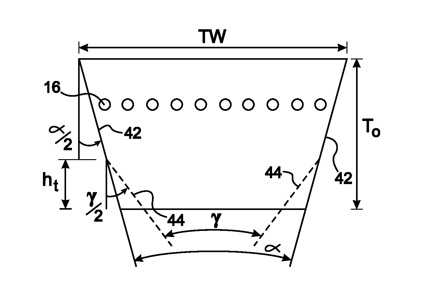
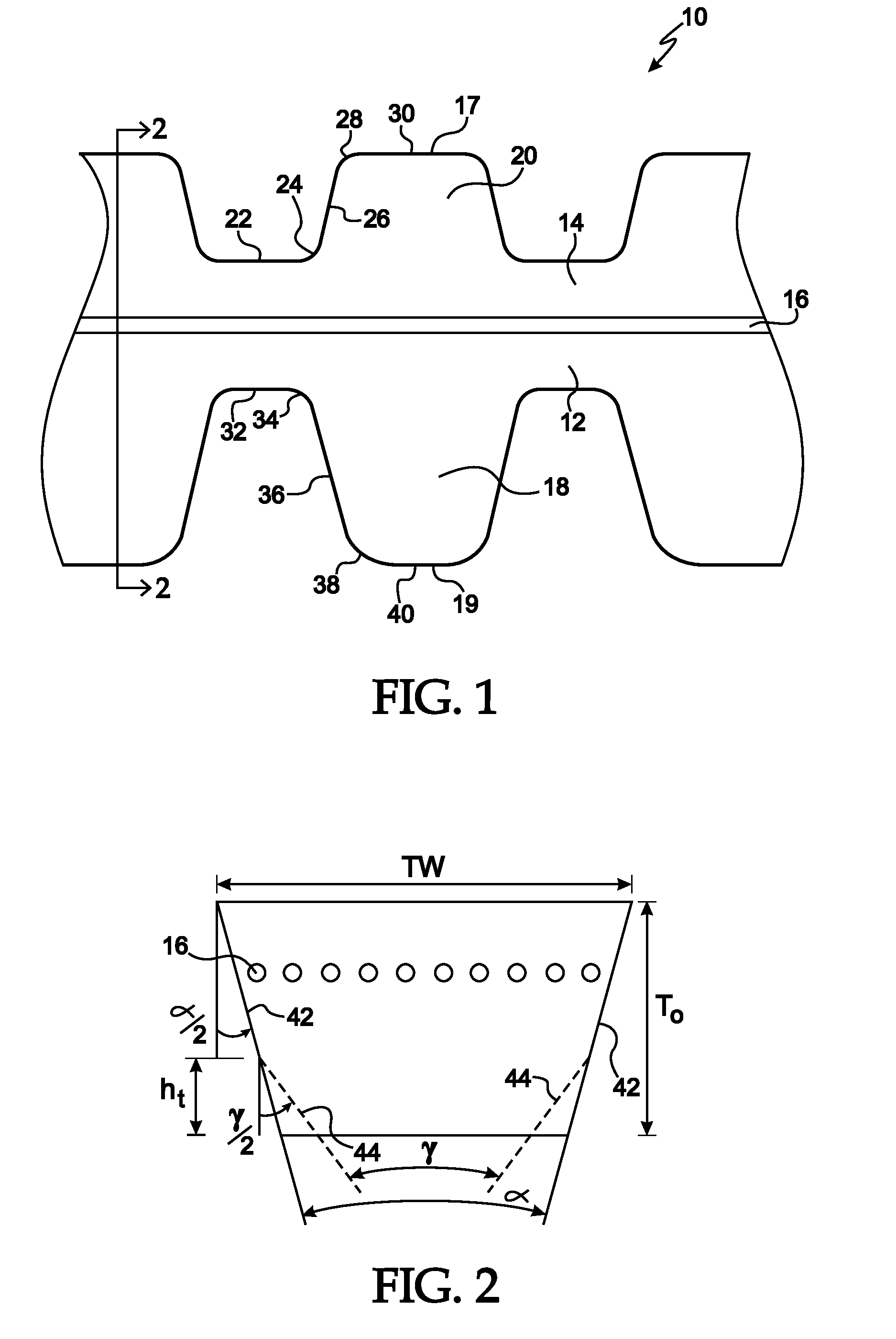
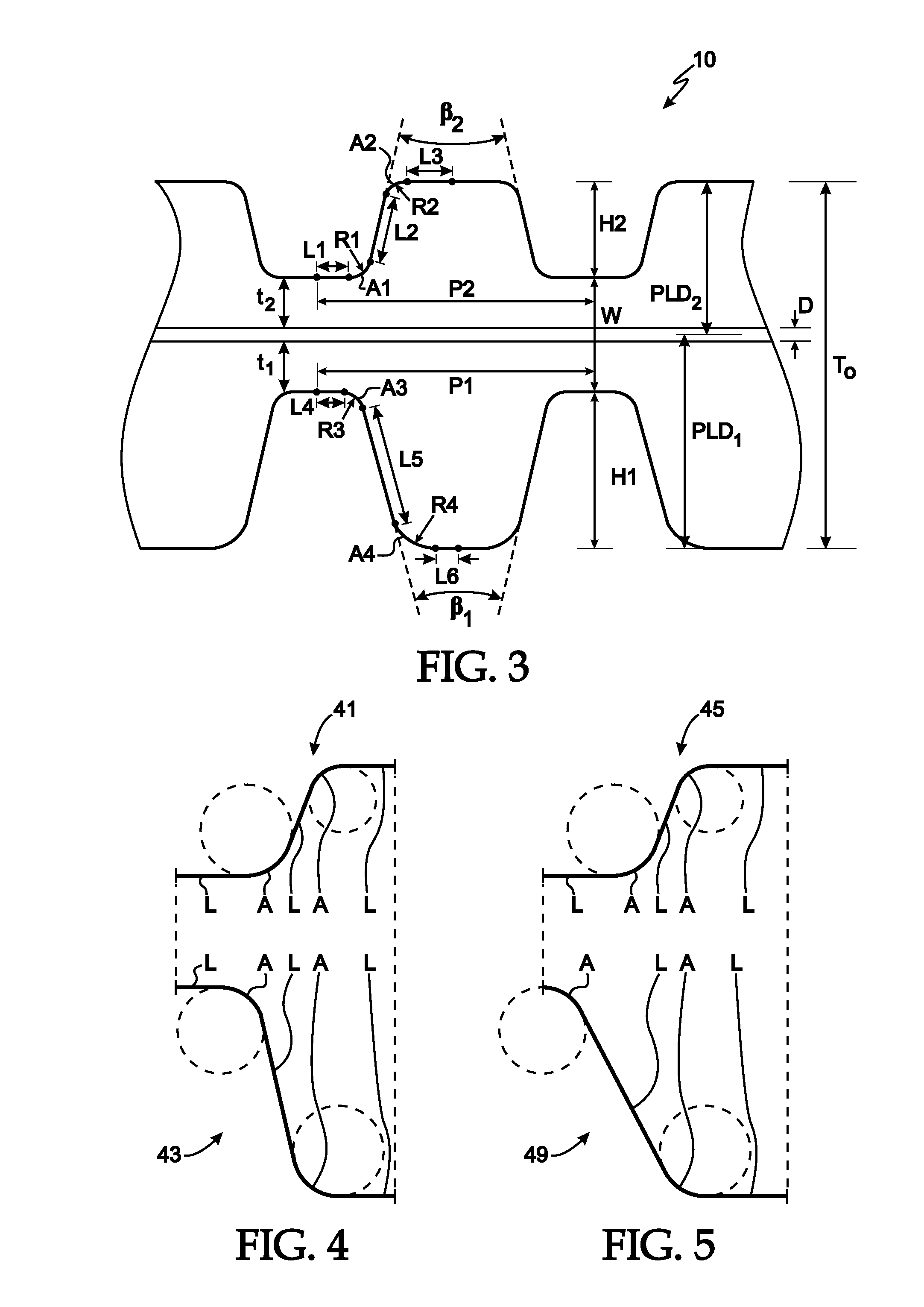
[0032]To achieve maximum performance, efficiency, and durability in a VST, the belt has to be designed with high flexibility but high transversal stiffness while maintaining proper side contact and low stress concentration. To satisfy these special requirements at some level, a V-belt may be adapted with a single set of lower cogs on the inside 40 of the belt. In a VST application requiring higher transmitting power, a double cogged V-belt design, in which additional cogs are added on the upper or back side 30 of a belt, may be used to further increase transversal stiffness while still maintaining high flexibility and suitable contact area. For both designs of single cog and double cog VST belts, optimal geometries of cog profiles and cord position are crucial but not easily discovered, as indicated by the large number of proposals found in the art.

[0033]Usually, the profile of each cog is symmetric about the cog center and is a combination of straight line segments and arcs. A nome...


PUM


Abstract

A double-cogged V-belt with the upper and lower cog profiles symmetric and having lines (“L”) and arcs (“A”) connected according to a sequence from the center of a root to the center of an adjacent cog of L1-A1-L2-A2-L3 for the upper profile and L4-A3-L5-A4-L6, and with at least one upper root and one lower root substantially aligned with each other, and with the sum of the length of L1 plus the radius of A1 equal to or within 20% of the sum of the length of L4 plus the radius of A3. The upper and lower pitches may be equal and all the roots aligned, or there may be more upper cogs than lower cogs. Some or all arcs and lines may be connected tangentially.

Description

BACKGROUND OF THE INVENTION[0001]1. Field of the Invention[0002]This invention relates generally to a double-cogged V-belt, more particularly to a double-cogged V-belt with aligned upper and lower cogs having a particular combination of cog profiles, and specifically such a V-belt adapted for a variable speed transmission.[0003]2. Description of the Prior Art[0004]The belt plays an important role in the operation of variable speed power transmission systems or drives, such as used in scooters, motorcycles, snowmobiles, all-terrain vehicles, cars and industrial applications. In one exemplary design of variable speed transmission (“VST”), the belt is a flexible element which connects two pairs of sheaves through friction to transmit power from the driving shaft to the driven shaft. Each pair of sheaves includes a fixed sheave and a movable sheave. By controlling the axial movement of movable sheaves, the speed and torque ratio may be changed. During operation, the belt sustains extrem...

Claims


Application Information

Patent Timeline
Patent Type & Authority Patents(United States)
IPC IPC(8): F16G5/20
CPCF16G5/20F16G1/28
Inventor FAN, XINJIANLU, WENLONGSATO, YOSHITAKA
Owner THE GATES CORP
Why Eureka
Try Eureka