
Methods and apparatus for distillation of shallow depth fluids

a technology of shallow depth fluid and method, applied in vacuum distillation separation, vessel construction, separation process, etc., can solve the problems of large power requirements, complex known distillation devices and methods,

Inactive Publication Date: 2012-06-26
HYDROLOGIC IND INC
View PDF32 Cites 16 Cited by
  • Summary
  • Abstract
  • Description
  • Claims
  • Application Information

AI Technical Summary

Benefits of technology

The system achieves efficient separation of substances with reduced energy consumption, capable of operating over a wide range of temperatures and pressures, producing high-purity distillates while minimizing energy requirements.

Problems solved by technology

Known distillation devices and methods, however, are often complex, operate at high pressures and / or temperatures, and require large quantities of power due to inefficiencies.

Method used


Image

  • Methods and apparatus for distillation of shallow depth fluids
  • Methods and apparatus for distillation of shallow depth fluids
  • Methods and apparatus for distillation of shallow depth fluids

Examples


Embodiment Construction

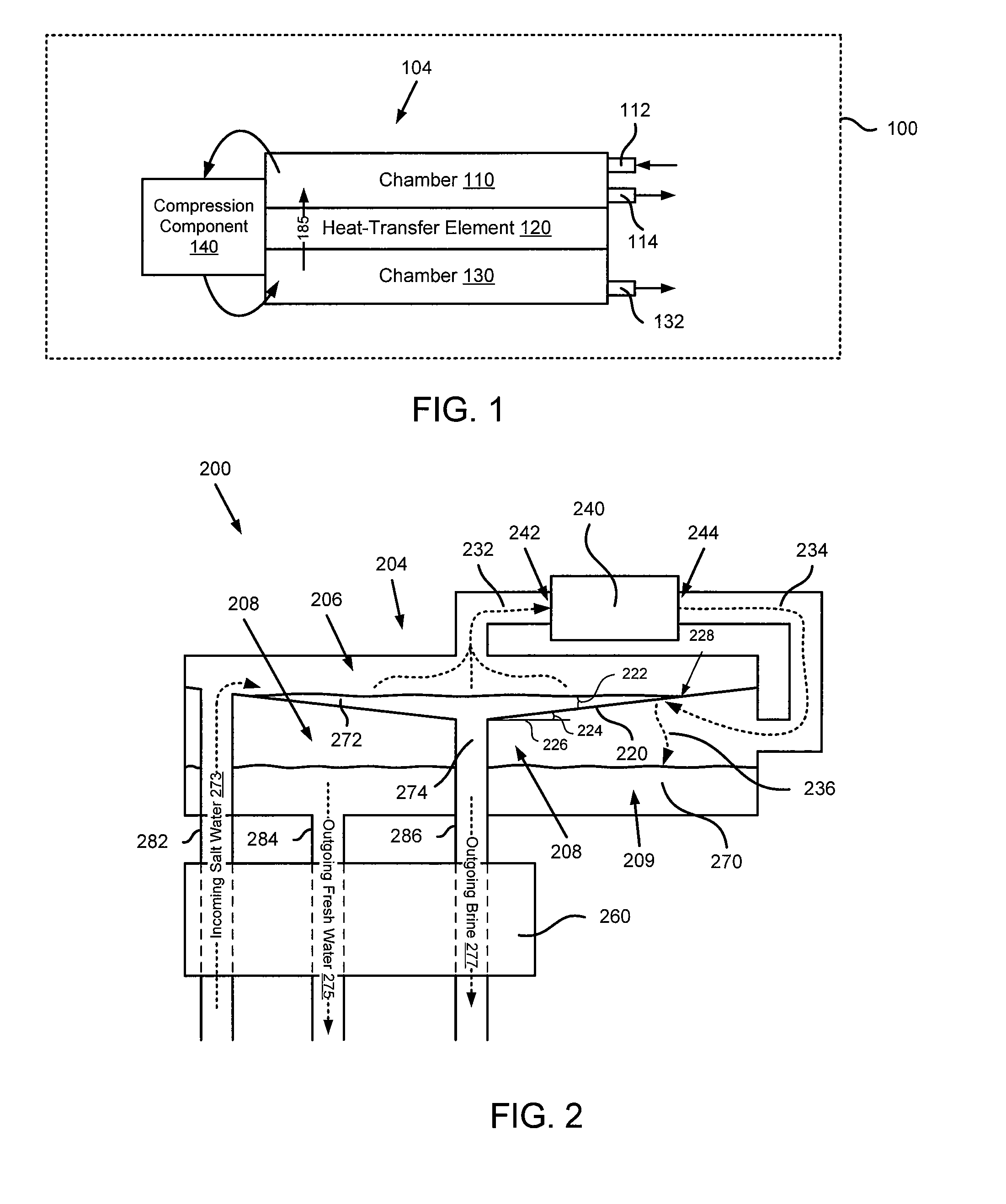
[0023]FIG. 1 is a schematic block diagram that illustrates a distillation system 100, according to an embodiment of the invention. In some embodiments, the distillation system can also be referred to as a distillation unit. The distillation system 100 is configured to re-use energy to efficiently separate a substance from a mixture of two or more substances. Specifically, energy that is released and / or added to the system during the separation process is utilized continuously to promote further separation in a cyclical fashion. In some embodiments, the distillation system can be a high efficiency distillation system that can have different portions that operate at different temperatures (e.g., at low temperature or at high temperature) and / or different pressures (e.g., at low pressure or at high pressure).

[0024]The distillation system 100 includes a heat-transfer element 120, a compression component 140, and two chambers-chamber 110 and chamber 130. The components of the distillatio...


PUM

PropertyMeasurementUnit
angleaaaaaaaaaa
angleaaaaaaaaaa
angleaaaaaaaaaa

Abstract

In one embodiment, an apparatus includes a housing that has at least an inlet and an outlet. The housing is configured to receive a volume of fluid via the inlet. The volume of fluid is in a substantially liquid state and at least a portion of the volume of fluid includes a dissolved impurity. The apparatus also includes a heat-transfer element coupled to an interior volume of the housing. The heat-transfer element includes a surface, at least a portion of which is disposed at an angle with respect to a horizontal plane. The volume of fluid includes a surface parallel to the horizontal plane. The apparatus further includes a compression component configured to compress at least a portion of fluid boiled from the volume of fluid.

Description

CROSS-REFERENCE TO RELATED APPLICATIONS[0001]This application claims priority to U.S. Provisional Application Ser. No. 60 / 864,899, entitled, “Liquid Purification System,” filed on Nov. 8, 2006, which is incorporated herein by reference in its entirety. This application is related to the following commonly owned and assigned applications: U.S. Patent Publication No. 2008 / 0105534, entitled “Methods and Apparatus for Distillation Using Phase Change Energy” filed on Nov. 7, 2007 and U.S. Patent Publication No. 2008 / 0105531 entitled “Methods and Apparatus for Signal Processing associated with Phase Change Distillation” filed on Nov. 7, 2007, both of which are incorporated herein by reference in their entireties.BACKGROUND[0002]Embodiments of the invention relate generally to distillation, and in particular, to methods and apparatus for efficient distillation over a wide range of temperatures and pressures.[0003]A number of known devices and methods have been utilized to distill (or separ...

Claims


Application Information

Patent Timeline
Patent Type & Authority Patents(United States)
IPC IPC(8): B01D1/28B01D5/00B01D3/10C02F1/04
CPCB01D1/0035B01D1/2887B01D1/2896B01D5/0051B01D5/006C02F1/048C02F1/14B01D3/06C02F1/06Y10S159/16Y10S159/40Y02W10/33Y02W10/37Y02A20/212
Inventor BURKE, FRANCIS P.HORNE, KENNETH J.TAYLOR, DAVID B.TOPAZ, STEPHEN R.
Owner HYDROLOGIC IND INC
Learn More