
Suspension substrate, suspension, head suspension and hard disk drive

a suspension substrate and head suspension technology, applied in the field of suspension substrates, can solve the problems of difficult to perfectly prevent warpage, occurrence of strain, suspension substrates, etc., and achieve the effect of reducing strain

Inactive Publication Date: 2012-06-26
DAI NIPPON PRINTING CO LTD
View PDF11 Cites 4 Cited by
  • Summary
  • Abstract
  • Description
  • Claims
  • Application Information

AI Technical Summary

Benefits of technology

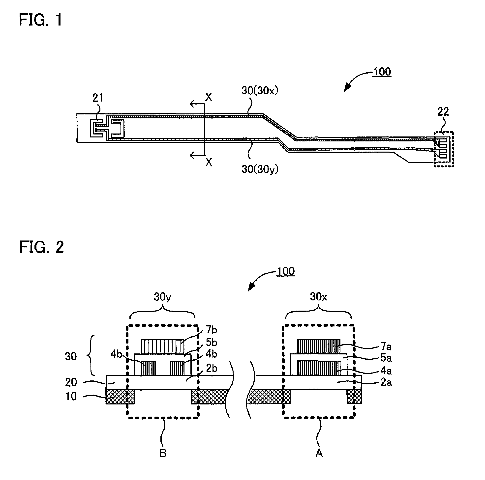
[0011]The present invention has been made in view of the above situation and it is a main object of the present invention to provide a suspension substrate having reduced strain.
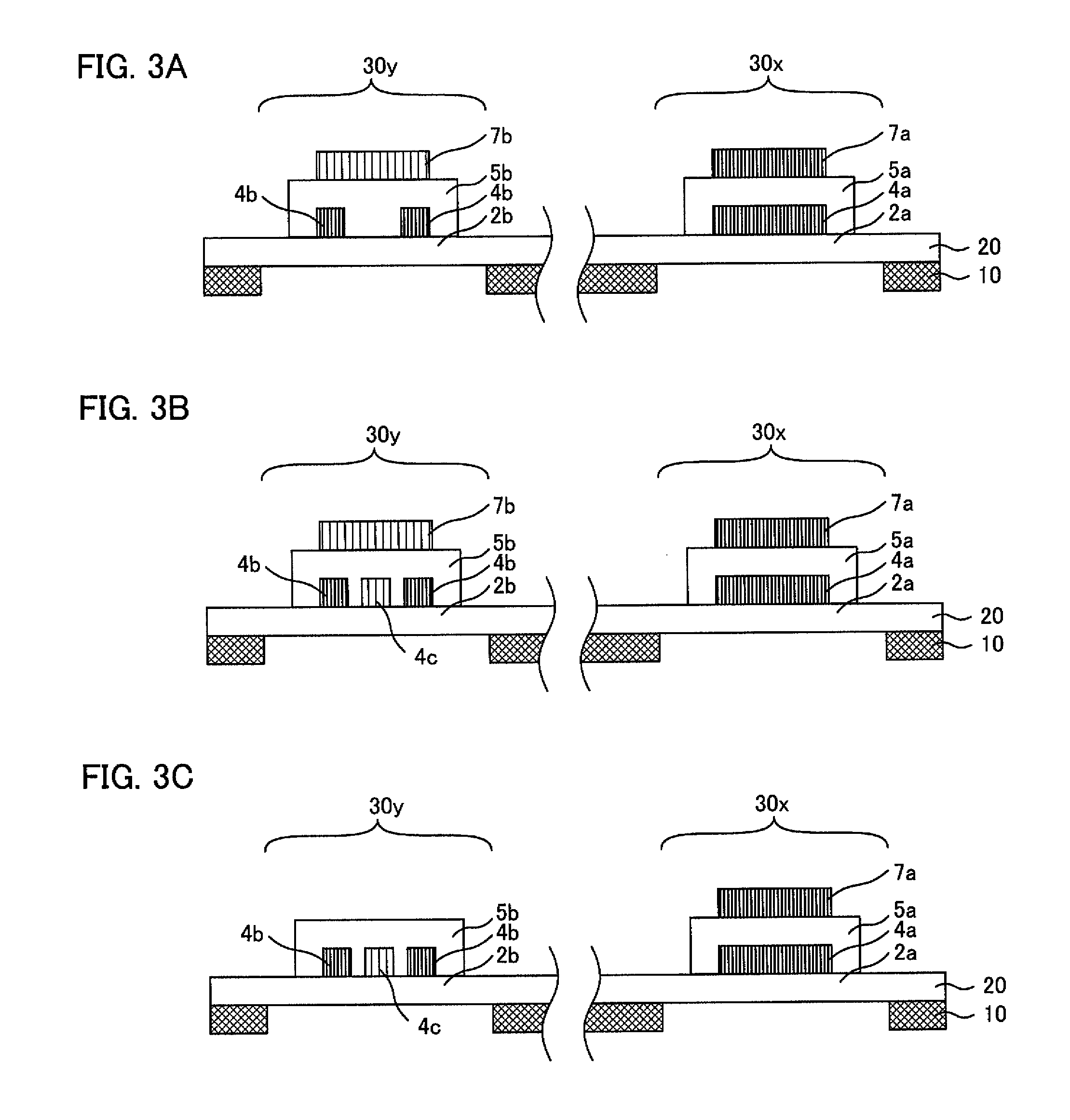
[0027]The present invention produces such an effect that a suspension substrate having reduced strain can be obtained.

Problems solved by technology

Therefore, this structure poses such a problem that the rigidity balance and weight balance of the whole suspension substrate are inferior, resulting in the occurrence of strain.
However, even in the case of using a material having a close linear expansion coefficient, it is difficult to perfectly prevent warpage caused by thermal shrinkage resulting from the heat history through which the suspension substrate is produced.
Moreover, when the wide wiring laminate structure and the narrow wiring monolayer structure are arranged at the right and left positions with respect to the center line of the suspension substrate, the suspension substrate is more outstandingly affected by thermal shrinkage, causing the warpage of the whole suspension more easily than when two narrow wiring monolayer structures are arranged at the right and left positions with respect to the center line of the suspension substrate.
This is because the wide wiring laminate structure has such rigid structural characteristics that two wirings are laminated through an insulation layer and also, two wirings are wide, so that this structure is outstandingly affected by thermal shrinkage.

Method used


Image

  • Suspension substrate, suspension, head suspension and hard disk drive
  • Suspension substrate, suspension, head suspension and hard disk drive
  • Suspension substrate, suspension, head suspension and hard disk drive

Examples


examples

[0113]The present invention will be explained in more detail by way of examples.

example

[0114]In this example, a suspension substrate provided with a wide wiring laminate structure and a narrow wiring-containing structure as shown in FIG. 7F was manufactured. First, a laminate substrate comprising a metal substrate / first insulation layer / seed layer / first conductive layer was prepared. Here, a laminate substrate comprising stainless as the metal substrate, a polyimide as the first insulation layer, and Cu as the seed layer and first conductive layer was prepared. Next, a metal etching resist was applied to the laminate substrate. Specifically, a metal etching resist layer was formed on each side of the laminate substrate and a resist pattern was formed by the photolithographic method. Here, a resist pattern corresponding to the wiring part is formed on the surface of the first conductive layer and a resist pattern corresponding to the jig hole and flying read part was formed on the surface of the metal substrate. Next, using an aqueous ferric chloride solution as the et...


PUM

PropertyMeasurementUnit
thicknessaaaaaaaaaa
thicknessaaaaaaaaaa
thicknessaaaaaaaaaa

Abstract

It is a primary object of the present invention to provide a suspension substrate having reduced strain. The present invention solves the problem by providing a suspension substrate comprising: a fundamental structure in which a metal substrate, a first insulation layer, and a wiring are laminated in this order; a wide wiring laminate structure provided with a wide wiring first insulation part of the first insulation layer, a first wide wiring formed on the wide wiring first insulation part, a second insulation part formed on the first wide wiring, and a second wide wiring formed on the second insulation part; and a narrow wiring-containing structure provided with a narrow wiring first insulation part of the first insulation layer and a first narrow wiring formed on the narrow wiring first insulation part, wherein the narrow wiring-containing structure is provided with a strain-limiting part formed to limit strain generated in relation to the wide wiring laminate structure.

Description

BACKGROUND OF THE INVENTION[0001]1. Field of the Invention[0002]The present invention relates to a suspension substrate used for a magnetic head suspension for a HDD, and, particularly, to a suspension substrate having reduced strain.[0003]2. Description of the Related Art[0004]In recent years, there have been great demands for increases in the amount of information processing and in information processing speed of a personal computer with, for example, the distribution of Internet. Along with this, it has become necessary for hard disc drives (HDD) incorporated into a personal computer to increase its capacity and its information communication speed. The magnetic head suspension used in this HDD is provided usually with a suspension substrate mounted with a magnetic head. Also, the suspension substrate is formed with wirings (read wiring and write wiring) made of conductive thin films to connect this magnetic head with the read / write wirings of the magnetic disc device.[0005]In cur...

Claims


Application Information

Patent Timeline
Patent Type & Authority Patents(United States)
IPC IPC(8): G11B5/48
CPCG11B5/486H05K1/0271H05K1/056H05K2201/09781H05K2201/0154H05K2201/09672H05K2201/09727H05K3/28
Inventor KAWANO, SHIGEKI
Owner DAI NIPPON PRINTING CO LTD
Learn More