
Decorative cap and nut for toilet base

Inactive Publication Date: 2012-07-03
GAGER DENNIS J
View PDF22 Cites 45 Cited by
  • Summary
  • Abstract
  • Description
  • Claims
  • Application Information

AI Technical Summary

Benefits of technology

[0006]The present invention is designed to overcome the deficiencies of the prior art discussed above. It is an object of the present invention to provide a decorative cap and nut for a toilet base that is easy to use.
[0008]It is a further object of the present invention to provide a decorative cap and nut for a toilet base that provides a watertight seal to prevent water from rusting the bolts holding the toilet in place.

Problems solved by technology

These caps, however, are frequently unsightly and are often displaced during cleaning of the toilet base because they typically extent upwardly a significance distance above the base.
The caps are not watertight, and rust on the bolts soon manifests itself.
Putty or adhesive has been placed on the caps to alleviate some of these problems, but that complicates access to the bolts if that ever becomes necessary.
Therefore, a need exists for a decorative cap and nut for toilet base that is effectively secures the toilet but which blends in with the toilet base, is waterproof and is not easily dislodged.

Method used


Image

  • Decorative cap and nut for toilet base
  • Decorative cap and nut for toilet base
  • Decorative cap and nut for toilet base

Examples


first embodiment

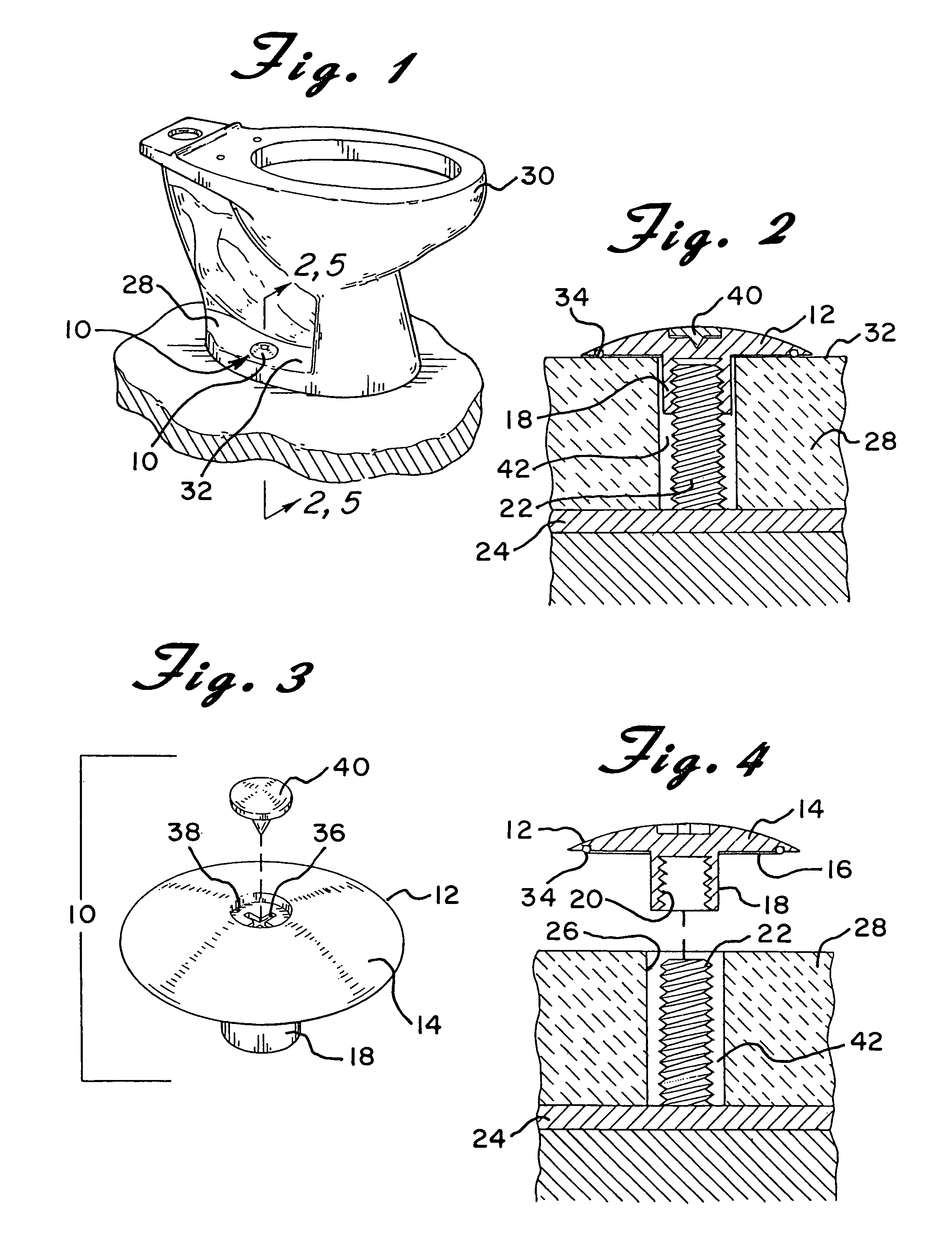
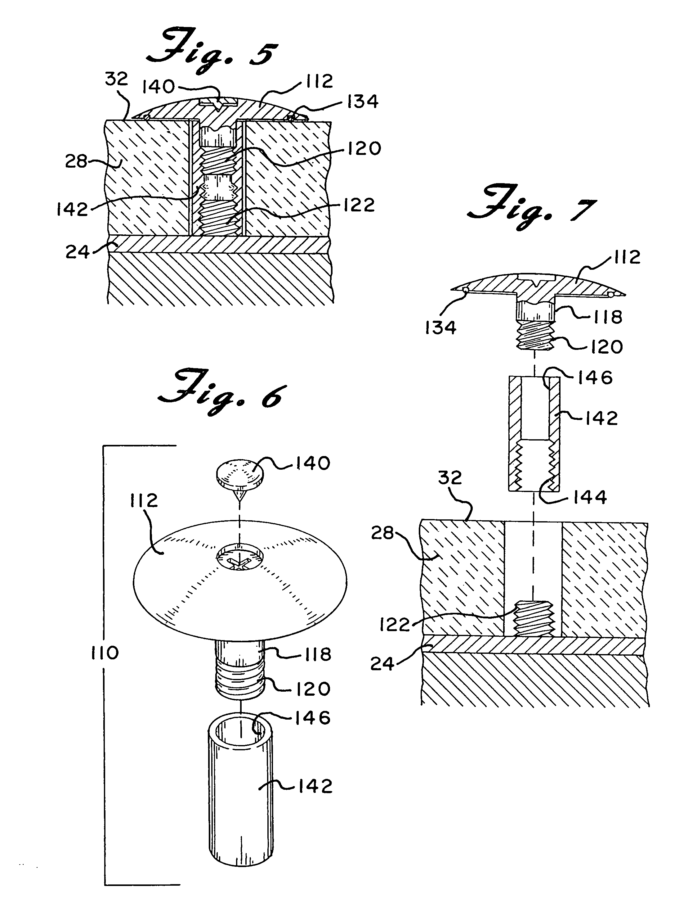
[0026]Referring now to the drawings in detail wherein like reference numerals have been used throughout the various figures to designate like elements, there is shown in FIG. 1 a decorative cap and nut for a toilet base constructed in accordance with the principles of the present invention and designated generally as 10.

[0027]The decorative cap and nut for toilet base 10 of the present invention essentially includes a top substantially disc-shaped member 12 having an upper disc surface 14 and a lower disc surface 16. Because the member 12 is essentially disc shaped, its diameter is substantially greater than its thickness. The advantage of this shape will be readily apparent.

[0028]A substantially cylindrically shaped stem 18 extends vertically downwardly from the lower surface 16 of the top 12. The cylindrically shaped stem 18 is preferably substantially coaxial with the top 12 and may be integrally formed therewith such as by molding or machining or the like. Preferably, the inside...

third embodiment

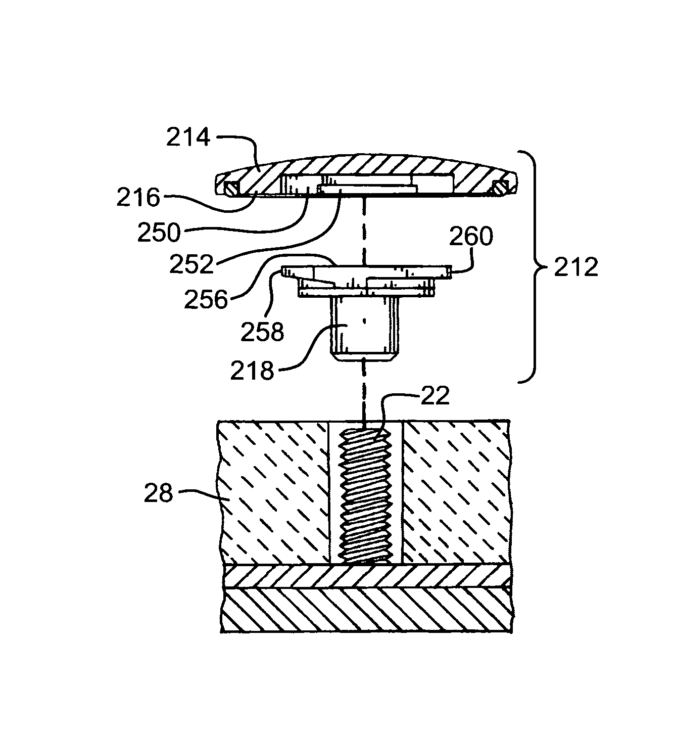
[0038]A third form of the invention is shown in FIGS. 8-13 wherein again substantially the same reference numerals are used to identify similar elements but are proceeded by a 2. In this third embodiment of the invention, the cap and nut of the previous embodiments are formed separately in two parts and are then joined together in use. The combination, identified at 210, includes a substantially disc-shaped cap member 212 and a nut 248.

[0039]The cap member 212 has an upper disc surface 214 and a lower disc surface 216. Because the member 212 is essentially disc shaped, its diameter is substantially greater than its thickness. The advantage of this shape is described above with reference to the first embodiments and is equally applicable here. As shown most clearly in FIGS. 9-13, the lower disc surface 216 includes an elongated opening 250 that leads to undercut areas 252 and 254 as shown in FIGS. 10 and 13.

[0040]The nut 248 includes a flat top 256 and a substantially cylindrically s...


PUM


Abstract

A decorative cap and nut for securing a toilet base to a floor includes a top substantially disc-shaped member having an upper disc surface and a lower disc surface. The diameter of said disc-shaped member is substantially greater than the thickness thereof so as to lie substantially flush with the toilet base. A coaxial cylindrically shaped stem extends vertically downwardly from the top and is connected to the lower disc surface. The stem includes an internal thread adapted to be threaded onto a floor bolt that extends upwardly through an aperture in the toilet base. A slot in the upper disc surface can be engaged by a tool for rotating the top and an O-ring located on the under disc surface seals the disc-shaped member to the upper surface of the toilet base. A plug fits within the slot to hide the same. The stem and top can be integrally formed in a single piece or can be made of more than one piece joined together.

Description

CROSS REFERENCE TO RELATED APPLICATIONS[0001]This application is a Continuation-in-Part of prior U.S. application Ser. No. 11 / 999,362, filed Dec. 5, 2007 now abandoned, which claims the benefit of prior U.S. Provisional Application Ser. No. 60 / 872,978, filed Dec. 6, 2006.BACKGROUND OF THE INVENTION[0002]The present invention is directed toward a decorative cap and nut for a toilet base and more particularly, toward a decorative cap and nut that will securely hold the toilet base to the floor, that blends in with the toilet base and that will not easily be dislodged.[0003]Toilets are typically mounted on two loosely mounted vertical bolts that extend upwardly from a circular flange secured to the floor. The mounting of the base of the toilet involves manually lowering the same so that the bolts extend through apertures in the base. When that is accomplished, nuts are tightened downwardly on the upper ends of the bolts against the base of the toilet to securely hold the toilet in plac...

Claims


Application Information

Patent Timeline
IPC IPC(8): F16B37/14
CPCE03D11/16F16B5/02F16B37/14
Inventor GAGER, DENNIS J.
Owner GAGER DENNIS J
Learn More