Dust remover

a technology of dust removal and dust removal chamber, which is applied in the direction of cleaning equipment, filtration separation, and separation processes, etc., can solve the problems of large air consumption, high running cost, and difficult removal of large dust particles

Inactive Publication Date: 2012-07-03
TRINC
View PDF1 Cites 18 Cited by
  • Summary
  • Abstract
  • Description
  • Claims
  • Application Information

AI Technical Summary

Benefits of technology

[0006]Therefore, it is an object of the present invention to provide a dust remover which is capable of removing dust in a large area, is efficient, is capable of reducing the consumptions of air and electric power, and does not contact the surface of the work to cause no damage.

Problems solved by technology

Furthermore, since in the other conventional dust remover, as shown in FIG. 8B and FIG. 9, the area of the work which the air or the ionized air is blown to is spot-like, the area of work to be dust removed is small or narrow, and thus the large-area dust removing is difficult.
Since air nozzles should be thickly disposed when large-area dust removing is carried out, large number of nozzles is required, the consumption of air becomes large, the running cost becomes high, and at the same time these become the problem as the waste of energy.
Furthermore, since the area of the work which the air or the ionized air is blown to is spot-like, in case that work 10 moves rapidly, the time for removing dust is short and thus the dust is not removed sufficiently.

Method used


Image

  • Dust remover
  • Dust remover
  • Dust remover

Examples


first embodiment

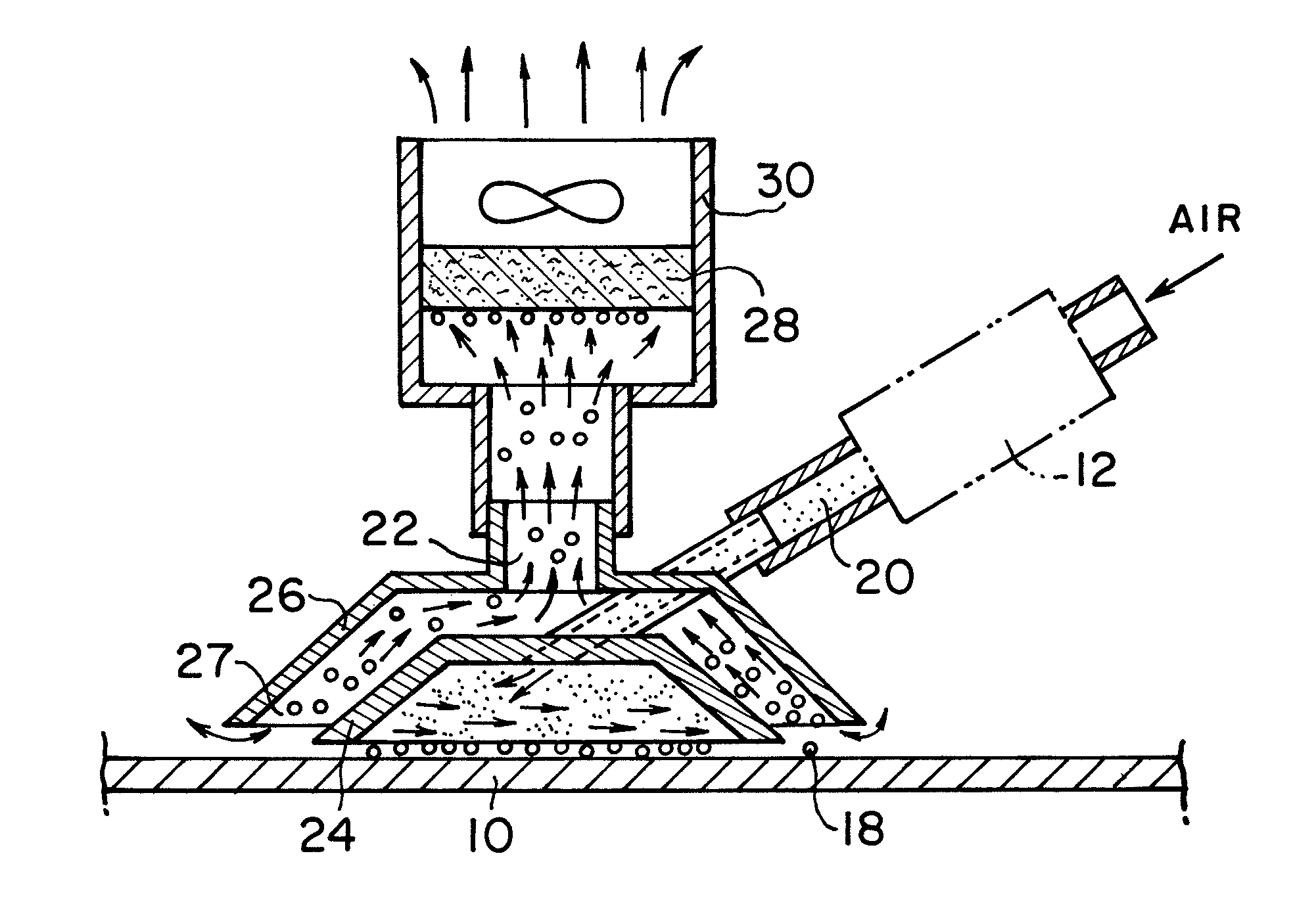
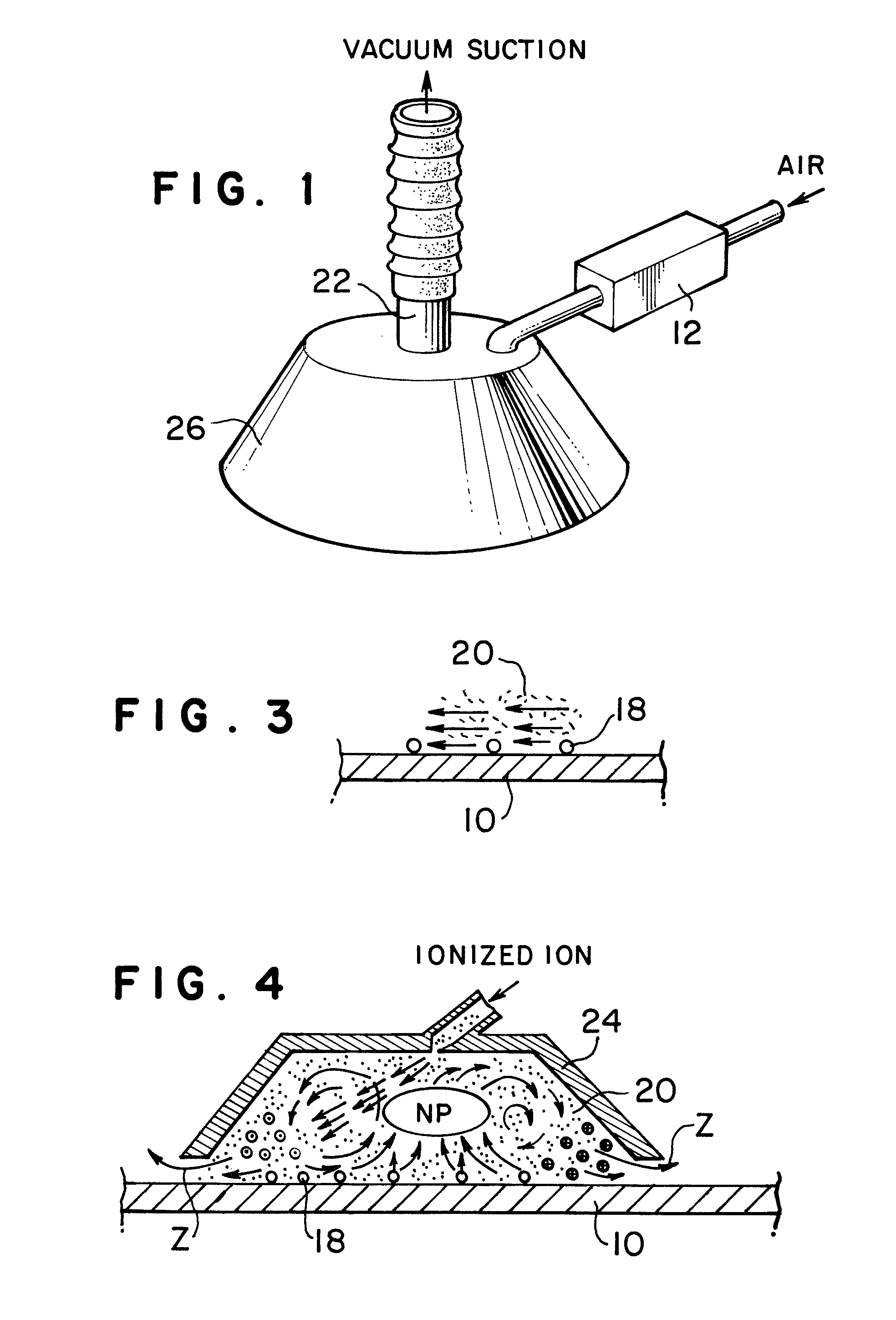
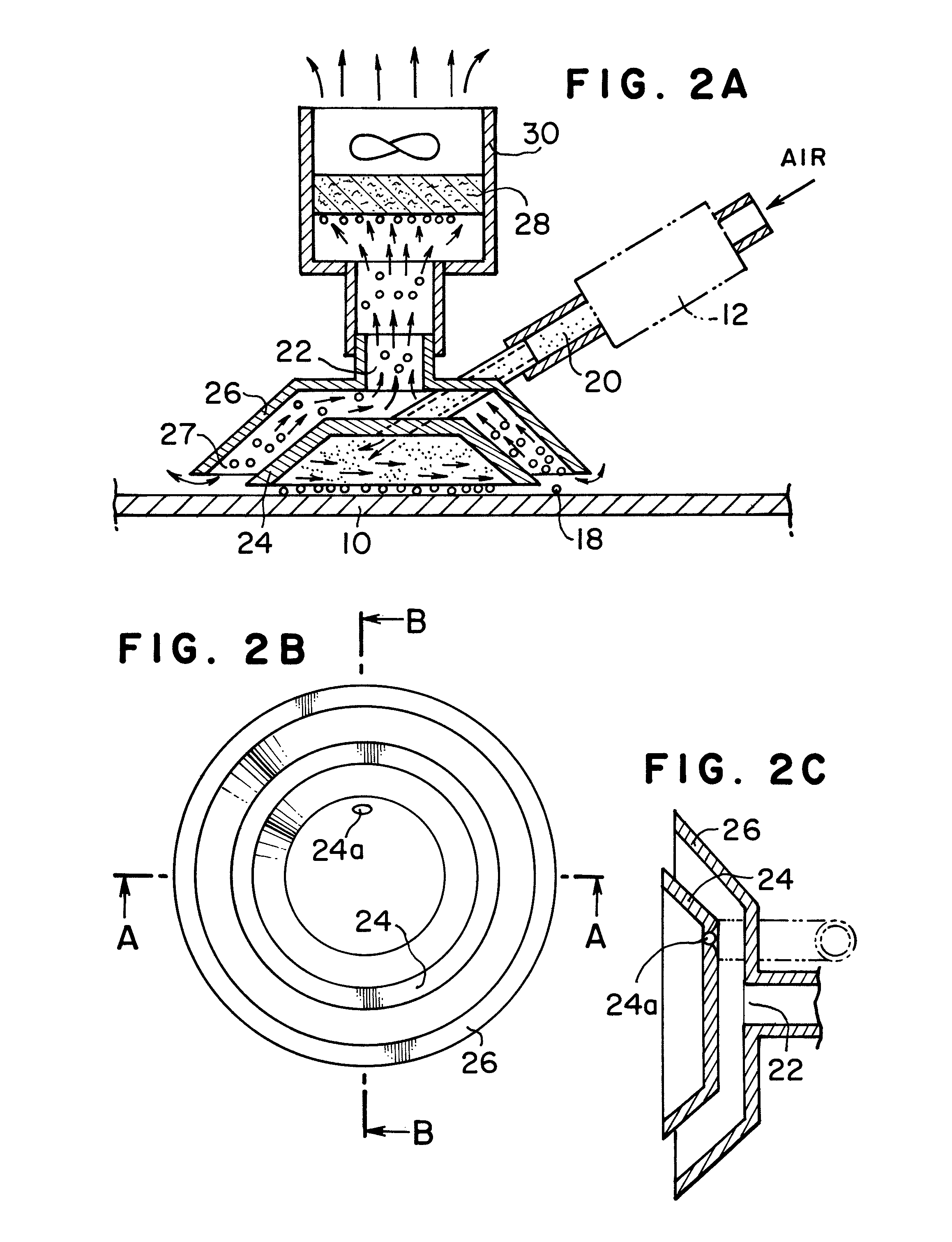
[0019]As shown in FIG. 1, in the first embodiment of dust remover according to the present invention, air is supplied into an internal container, not shown, disposed within a container 26 or air is supplied to ions generated by an ionizer 12 which may be provided as an option to produce ionized air, and then ionized air thus obtained is supplied into the internal container, not shown, disposed within the container 26. By supplying air or ionized air into the internal container, cyclone of air or ionized air is generated within the internal container. In case of ionized air, the work and dust on the work are electrostatically eliminated to get rid of attraction power between the dust and the work and at the same time the dust on the work is pushed outward from the peripheral portion of the internal container. The dust thus pushed is sucked through flow passage, not shown, between the container 26 and the internal container, and through a suction opening 22. As a result the dust is re...

second embodiment

[0024]As shown in FIG. 5, in the second embodiment the ionizer 12 as an option, a plurality of dust removing units and dust sucking container are used. Each of dust removing units corresponds to the small container 24 as explained with reference to FIGS. 2 and 4. Each small container 24 is supplied with ionized air from one or plural ionizer 12 and the cyclone is generated within the small container and thus dust on the surface of the work is pushed to the peripheral portion of the small container. In the second embodiment, Instead of the big container 26 used together with each small container, a single dust sucking container 52 in the form of hollow cubic shape is used. The dust which is pushed out from the small containers is sucked through the aperture 52a.

[0025]A plurality of dust removing units are disposed so that they cover the whole surface area of the work in the direction of movement of work. For example, the dust removing units are disposed in a zigzag manner in the dir...

third embodiment

[0026]As shown in FIG. 6, a plurality of dust removers or dust removing units, hereinafter referred to as a dust removing assembly, are disposed above the work such as carpet in non-contact state so as to be operated. Non-contact operation can avoid the problems such as interruption of suction or interruption of movement of the work or the like that would occur when operation is made in contact state. In the embodiment, the dust removing assembly is moved in non-contact with the work. In case of dust remover, small container 24 and big container 26 are provided, and in case of dust removing unit, small container 24 is provided. Furthermore, when the work is picked up or stripped off, by raising amount of air above the dust removing operation the cyclone is caused to destroy. Although the conventional usual cleaner varies suction power to change the dust removing amount, in the present dust removing assembly the dust removing amount is controlled by changing air output when air is su...


PUM

PropertyMeasurementUnit
speedaaaaaaaaaa
shapeaaaaaaaaaa
diametersaaaaaaaaaa

Abstract

A dust remover includes a small container disposed above a work, an aperture provided on the small container. Air is supplied through the aperture to generate high-speed cyclone within the small container. A big container is formed with a suction opening through which dust containing air is sucked out and disposed above the small container to form a flow passage between the small container and the big container. A suction equipment is provided to suck dust containing air through the suction opening of the big container.

Description

TECHNICAL FIELD[0001]This invention relates to a dust remover, and more particularly a dust remover using a mere air, and a dust remover using an ion containing air for removing dust and eliminating electricity simultaneously. In the specification they will be called a dust remover. Furthermore, in order to avoid overlapping description in the specification, the dust remover using a mere air and the dust remover using as an option an ionizer or an ion generator for introducing ions into an air will be explained at the same time. Although an object from which the dust is removed or an object from which the dust is removed and simultaneously electricity is eliminated includes a work, a carpet, a curtain and the like, the object will be called work.BACKGROUND OF INVENTION[0002]As shown in FIG. 8A, there is one conventional dust remover is moved on the surface of the work 10. The dust 18 on the work 10 is stripped off by a rotating brush 11 and the wind of vacuum suction. As shown in FI...

Claims


Application Information

Patent Timeline
Patent Type & Authority Patents(United States)
IPC IPC(8): B01D50/00
CPCB08B5/02B08B6/00B08B15/04B08B9/286A47L9/02A47L9/10A47L9/16A47L7/00
Inventor TAKAYANAGI, MAKOTO
Owner TRINC
Why Eureka
Try Eureka