Computational imaging system

a technology of computation and imaging system, applied in the field of computation-based imaging system, can solve the problems of large amount of light loss, difficult to sharply capture object scenes that span large distances,

Inactive Publication Date: 2012-07-03
GOLD CHARM LTD
View PDF27 Cites 162 Cited by
  • Summary
  • Abstract
  • Description
  • Claims
  • Application Information

AI Technical Summary

Problems solved by technology

Therefore, it is difficult to sharply capture object scenes that span large distances.
However, to blur the intermediate image, the coded aperture (e.g

Method used


Image

  • Computational imaging system
  • Computational imaging system
  • Computational imaging system

Examples


Embodiment Construction

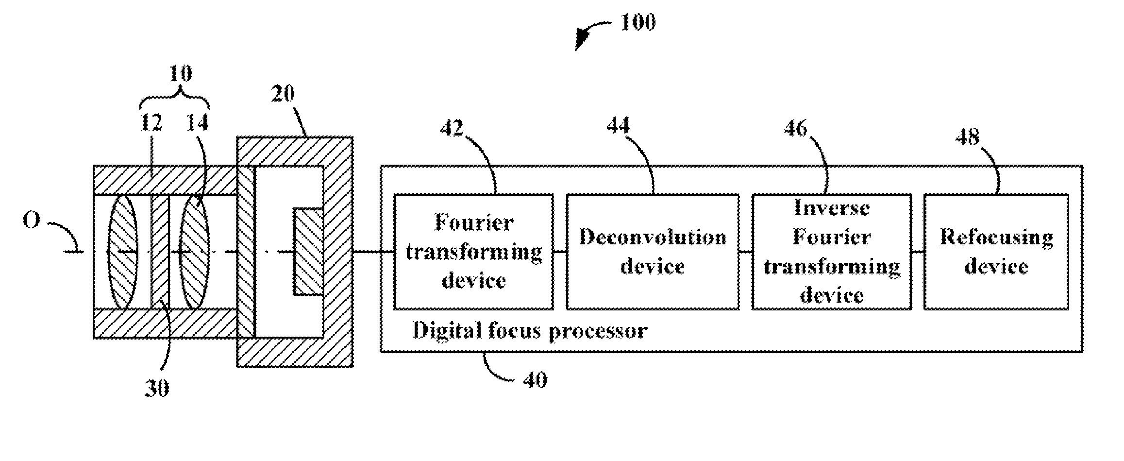
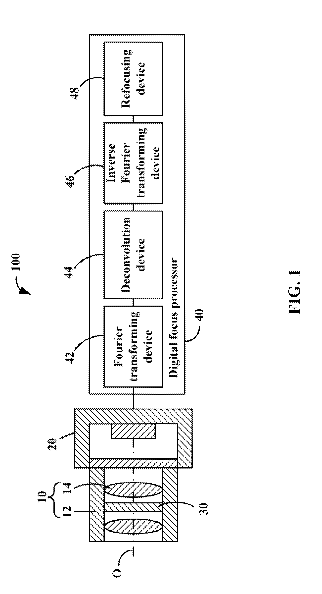
[0012]Embodiments of the present computational imaging system will now be described in detail with reference to the drawings.

[0013]Referring to FIGS. 1 and 2, a computational imaging system 100, according to a first embodiment, includes a lens 10, an image sensor 20, an LC element 30, and a digital focus processor 40.

[0014]The lens 10 and the image sensor 20 constitute an imaging sub-system. The LC element 30 functions as the aperture of the imaging sub-system constituted by the lens 10 and the image sensor 20 (placed in the light path of the imaging sub-system).

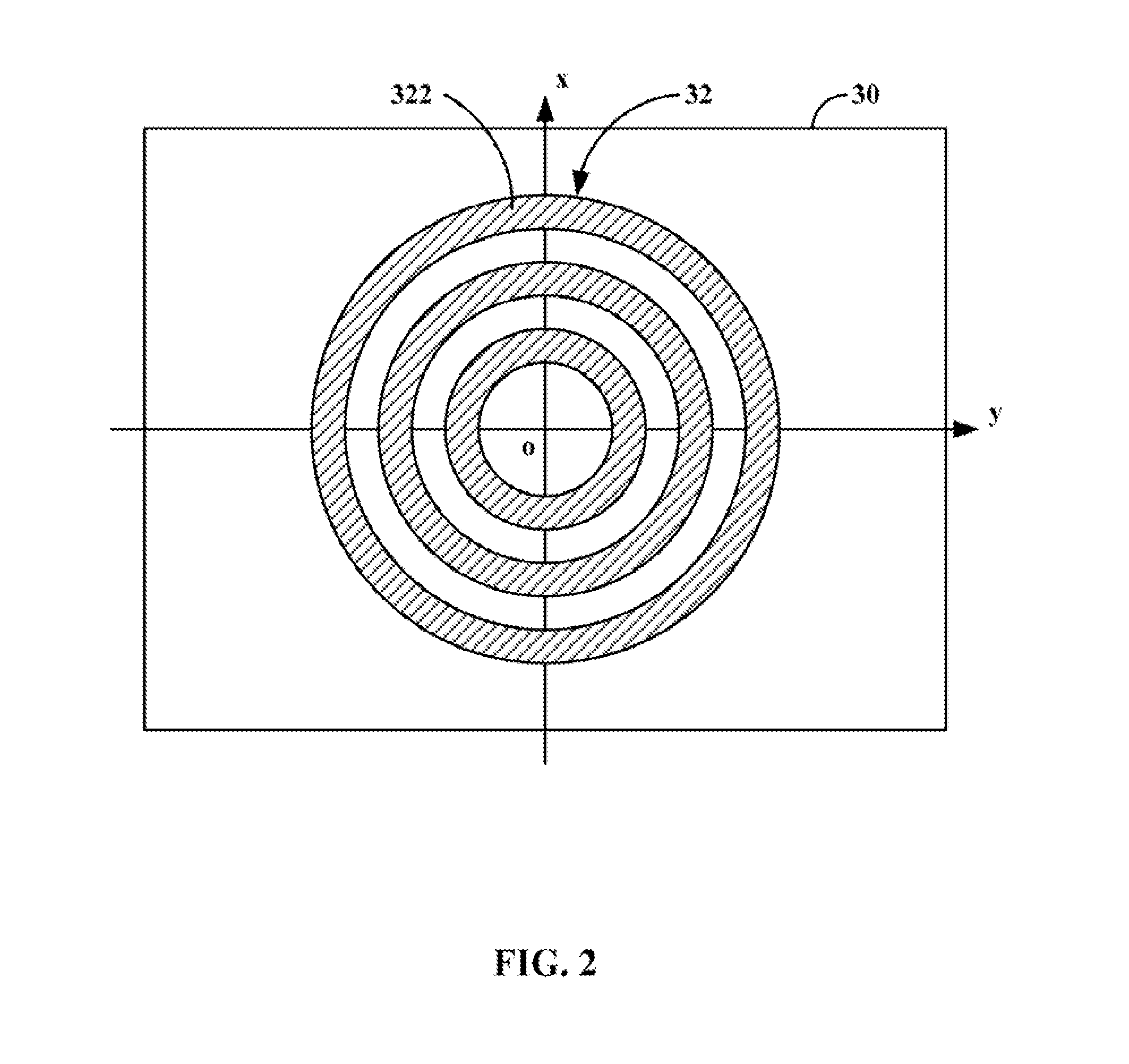
[0015]The LC element 30 is a transmissive LC panel that has a periodically patterned electrode 32. The electrode 32 is patterned according to a periodical modulation transfer function (i.e., a spatial function):

H(x,y)=cos 2π(sxx+syy),  (1)

where an origin of the oxy coordinate system is the center of the LC element 30, the x axis extends along the widthwise direction of the LC element 30, the y axis extends along the lengthwi...


PUM


Abstract

An imaging sub-system, a liquid crystal (LC) element, and a digital focus processor are provided. The LC element is placed in the light path of the imaging sub-system, functioning as the aperture of the imaging sub-system, and includes a periodically patterned electrode which is patterned according to a periodical modulation function and configured to blur an intermediate image captured by the imaging sub-system by applying a controllable voltage thereto. The digital focus processor is configured to deconvolute the periodical modulation function to remove the blur away from the intermediate image and determine an all-in-focus real image.

Description

BACKGROUND[0001]1. Technical Field[0002]The present disclosure relates to imaging systems and, particularly, to a computational imaging system.[0003]2. Description of Related Art[0004]Generally, an image of an object captured by conventional imaging systems is in focus only over a limited object distance range which is known as depth of field (DOF). Therefore, it is difficult to sharply capture object scenes that span large distances. To obtain an extended DOF, one attempt has been made that deliberately blurs an intermediate image captured by an imaging system by placing a coded aperture in the aperture of the imaging system and then digitally removes the blur using reconstruction algorithms. The coded aperture is patterned according to a modulation transfer function (e.g., a delta function). As such, reconstruction algorithms can effectively deconvolute the modulation transfer function and restores the image to a more recognizable likeness of the object with a greater DOF than wha...

Claims


Application Information

Patent Timeline
IPC IPC(8): H04N5/232G03B13/00G06K9/36H01L27/00H04N5/238H04N5/225
CPCH04N5/2254H04N5/23212G02B5/3016
Inventor CHIU, CHI-WEI
Owner GOLD CHARM LTD
Why Eureka
Try Eureka