Rapid super-resolution micro-imaging method and device

A microscopic imaging and super-resolution technology, which is applied in the field of optical super-resolution microscopy, can solve the problems of limiting FED imaging speed and achieve the effect of improving imaging speed and simple system structure

Inactive Publication Date: 2015-05-13
ZHEJIANG UNIV
View PDF3 Cites 22 Cited by
  • Summary
  • Abstract
  • Description
  • Claims
  • Application Information

AI Technical Summary

Problems solved by technology

Although FED has a relatively high signal-to-noise ratio and imaging speed, and the system is relatively simple a...

Method used


Image

  • Rapid super-resolution micro-imaging method and device
  • Rapid super-resolution micro-imaging method and device
  • Rapid super-resolution micro-imaging method and device

Examples


Embodiment Construction

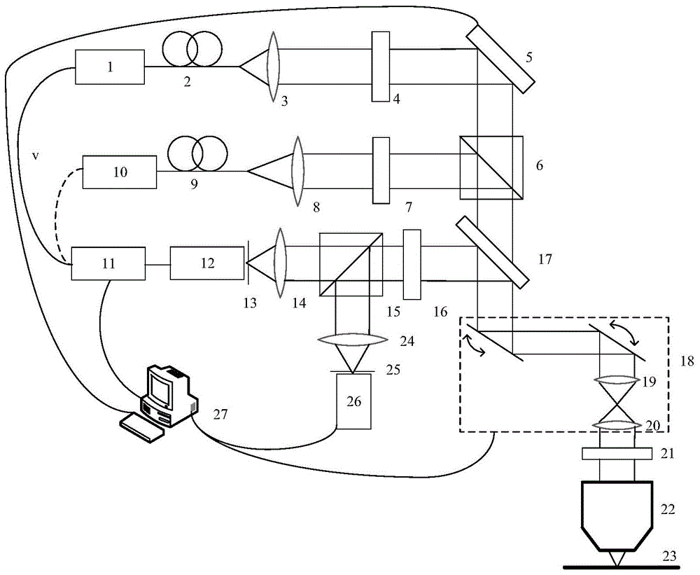
[0056] like figure 1 As shown, a fast super-resolution microscopic imaging device includes: laser 1, laser 10, single-mode fiber 2, single-mode fiber 9, collimator lens 3, collimator lens 8, polarizer 4, polarizer 7. Spatial light modulator 5, beam splitting prism 6, lock-in detection module 11 (including reference signal generator and lock-in amplifier), detector 12, detector 26, pinhole 13, pinhole 25, focusing lens 14, Focusing lens 24, beam splitting prism 15, bandpass filter 16, dichroic mirror 17, scanning galvanometer system 18, scanning lens 19, field lens 20, 1 / 4 wave plate 21, microscope objective lens 22, sample stage 23, controller 27.

[0057] Single-mode fiber 2, collimator lens 3, polarizer 4, and spatial light modulator 5 are sequentially located on the optical axis of the outgoing beam of laser 1, the light transmission axis of polarizer 4 is parallel to the horizontal direction, and laser 1 is connected to a phase-locked detector module, the beam is modulat...


PUM


Abstract

The invention discloses a rapid super-resolution micro-imaging method which comprises the following steps: modulating a first light beam and a second light beam according to corresponding modulation functions; combining the light beams into a path of light by using a beam splitter prism; radiating to the surface of a sample; collecting signal light emitted from different scanning points of the sample to be detected; dividing the signal light into two bundles, wherein the first light beam and the second light beam are imaged simultaneously; controlling the fragrance of the first light beam to be v, by taking the fragrance v as a reference signal, extracting signal light intensity I1(x, y) corresponding to the first light beam from one bundle of the signal light according to the reference signal, and by taking intensity of the other bundle of the signal light as I0(x, y), calculating the signal light intensity I2(x, y)=I0(x, y)-I1(x, y) corresponding to the second light beam, and achieving super-resolution imaging by using final effective signal light intensity I (x, y), wherein x and y are two-dimensional coordinates of the scanning points. The invention further discloses a rapid super-resolution micro-imaging device. As conventional respective imaging of hollow spots and solid spots is converted into simultaneous imaging, the scanning speed is accelerated while the transverse resolution is not changed.

Description

technical field [0001] The invention relates to the field of optical super-resolution microscopy, in particular to a fast super-resolution microscopic imaging method and device. Background technique [0002] For a long time, far-field optical fluorescence microscopy has been the most commonly used observation tool in life sciences due to its advantages of non-contact, non-damage, and ability to detect the interior of samples. However, due to the existence of the diffraction limit, the horizontal and vertical resolutions of traditional optical microscopes are only about 230nm and 500nm respectively. [0003] In order to reveal the dynamic and structural characteristics of the molecular scale in cells, improving the resolution of optical microscopy has become an urgent requirement for the development of life sciences. On the basis of far-field fluorescence microscopy, scientists have developed many practical methods to improve the resolution or even exceed the resolution limit...

Claims


Application Information

Patent Timeline
IPC IPC(8): G01N21/17G01N21/64G02B21/06
Inventor 匡翠方朱大钊王轶凡刘旭
Owner ZHEJIANG UNIV
Why Eureka
Try Eureka