
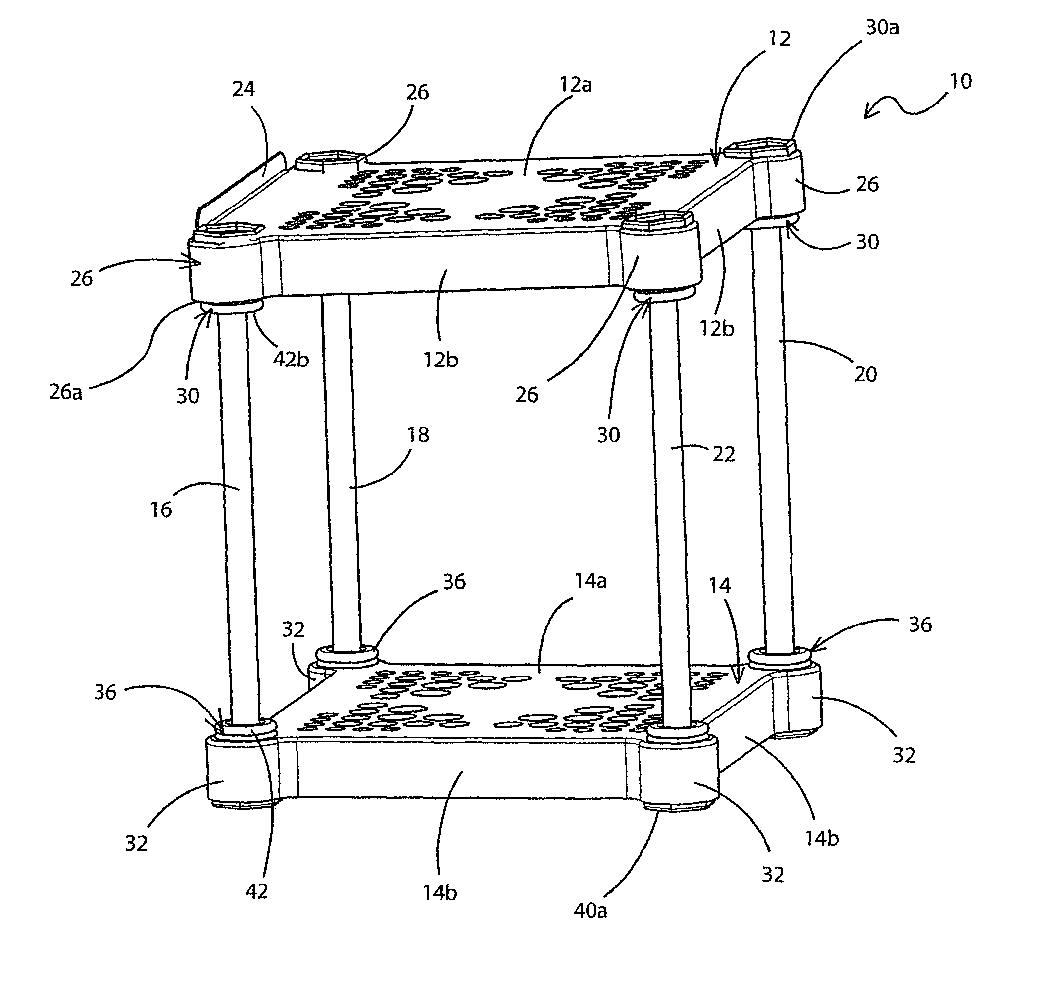
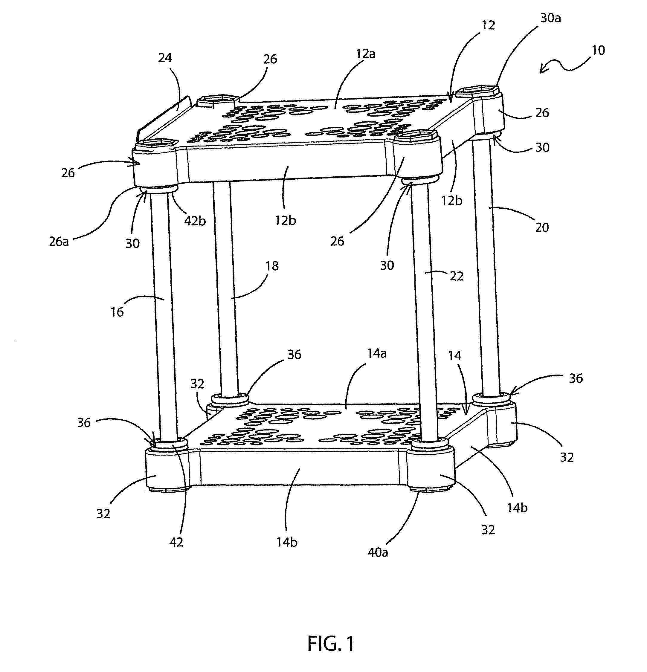
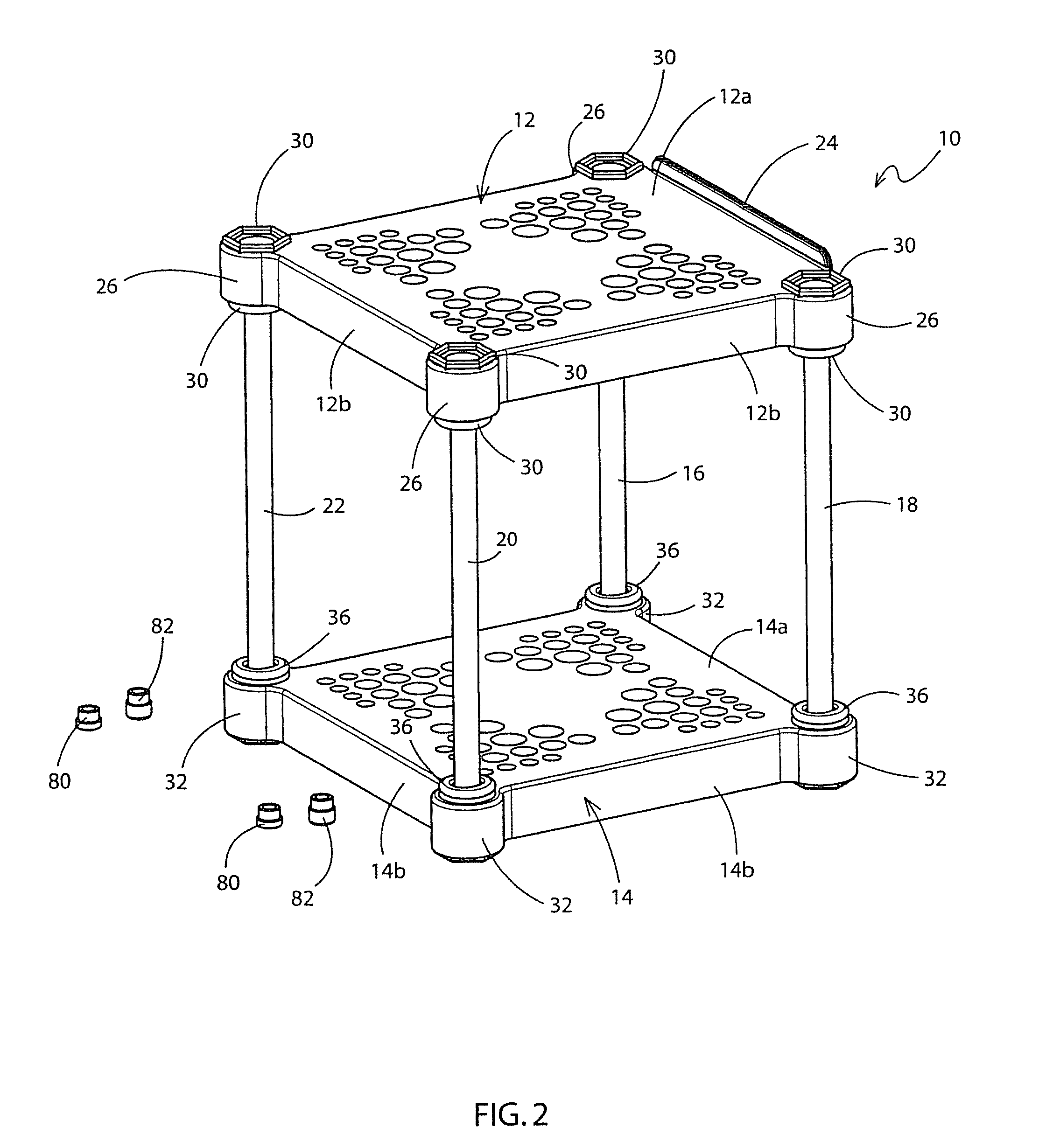
Vibration damping stand

a technology of vibration damping and support stands, which is applied in the field of furniture, can solve the problems of large speakers that cannot be placed on support or shelves, speakers may not be positioned at an appropriate height, and can move a considerable amount of air back and forth,

Active Publication Date: 2012-07-10
D MORRISON CONSULTING
View PDF24 Cites 33 Cited by
  • Summary
  • Abstract
  • Description
  • Claims
  • Application Information

AI Technical Summary

Benefits of technology

"The present invention is a stand that can hold an object above a surface and reduce its vibration. The stand has a frame with resilient bushings that hold rods. These rods move in the bushings and touch the surface. The rods can be protected from damage. The technical effect of this invention is to provide a stand that can hold objects securely and comfortably while reducing vibration."

Problems solved by technology

Large speakers for audio and home entertainment systems frequently cannot be placed on stands or shelves as they are too heavy in that they sometimes weigh as much as 30 lbs.
This means that the speakers may not be able to be positioned at an appropriate height to direct sound waves toward the listeners in a room.
Even if a speaker can be placed on a stand, high-powered speakers, especially large low frequency bass speakers, move a considerable amount of air back and forth.
This low frequency energy may generate considerable vibrations in the speaker and cause it to move forward and rearward across a surface.
This migration places the speaker at risk if it is supported a distance above a surface.
Furthermore, if the speaker cabinet is not rigidly bolted to a heavy mass or to its support, the support itself may vibrate with the speaker and possibly generate additional unwanted noise that ruins the sound quality.

Method used


Image

  • Vibration damping stand
  • Vibration damping stand
  • Vibration damping stand

Examples


second embodiment

[0044]Referring to FIGS. 16 and 17, there is shown a speaker stand in accordance with the present invention and generally indicated at 110. Stand 110 comprises a support frame 112 having four frame members 113. Each frame member 113 is an elongate, tubular member. Frame members 113 are coplanar with each other and are connected end-to-end in such a manner that they surround and define a space 115 between them. In accordance with a specific feature of the present invention, a projection 126 is interposed between the ends of adjacent pairs of frame members 113. As shown in FIG. 16, the exterior surface of projections 126 is arcuate or rounded in shape. A portion of each projection 126 extends upwardly for a distance beyond an upper surface of each frame member 113. Furthermore, a portion of each projection 126 extends downwardly for a distance beyond a lower surface of each frame member 113.

[0045]Support frame 112 is generally rectangular in shape and the projections 126 are disposed ...

first embodiment

[0051]It will be understood that one or more of adjuster plugs (80, 82), which were discussed with reference to the invention, may be placed into the bores of one or more of the bushings 130. These adjuster plugs will keep the first end of rods 116-122 spaced a distance away from the second end of the bore. This effectively increases the length of the rod 116-122 that projects outwardly away from the bore and thus increases the space between the lower surface of the support frame 112 and the support surface 100. The adjuster plugs may be placed into the bores of only two of the bushings 130, for instance those bushings receiving rods 116, 122 therein. This would then effectively increase the length of rods 116, 122 extending outwardly from the lower surface of one side of support frame 112 and therefore create an angled upper surface on support frame 112. The stereo speaker 125 would therefore be retained on stand 110 at an angle to the horizontal.

[0052]As indicated above, the bores...


PUM


Abstract

A stand for supporting an article a spaced distance above a support surface and for damping vibration therebetween. The stand includes a support frame having resilient bushings engaged therewith. Each bushing defines a bore into which a first end of one of a plurality of rods is received. The rods extend downwardly from the bushings and abut the support surface. The bores are configured to permit the rods to move more in one horizontal direction than in another.

Description

CROSS-REFERENCE TO RELATED APPLICATIONS[0001]This is a continuation-in-part of U.S. patent application Ser. No. 11 / 811,091, filed Jun. 8, 2007, the entire specification of which is incorporated herein by reference.BACKGROUND OF THE INVENTION[0002]1. Technical Field[0003]This invention generally relates to furniture. More particularly, the invention relates to support stands for stereo equipment. Specifically, the invention relates to a support stand for large stereo speakers that includes a mechanism to enable the stand to move slightly back and forth in response to vibrations in the speaker and air movement adjacent the same and to isolate that movement from the surface upon which the stand rests, and polarize that movement to enable the speaker to move more in one direction than in another direction.[0004]2. Background Information[0005]When a sound system is being set up in a room, consideration has to be given to the positioning of various speakers in the system so that sound emi...

Claims


Application Information

Patent Timeline
Patent Type & Authority Patents(United States)
IPC IPC(8): A47B7/00
CPCF16F1/3732F16F15/08H04R1/026
Inventor MORRISON, DAVIDDICKIE, ROBERT G.
Owner D MORRISON CONSULTING
Learn More