Optical catheter with rotary optical cap

a technology of optical caps and optical catheters, applied in the field of optical catheters, can solve the problems of non-uniform rotational distortion, scanning errors during measurement, and almost impossible post-processing calibration and compensation

Inactive Publication Date: 2012-07-10
NAT RES COUNCIL OF CANADA
View PDF10 Cites 16 Cited by
  • Summary
  • Abstract
  • Description
  • Claims
  • Application Information

AI Technical Summary

Problems solved by technology

In application, the rotation at the inserted end of the fibre suffers from non-uniform movements, which directly results in scanning errors during the measurement (non-uniform rotational distortion).
Because those errors appear to be random, it is almost impossible to calibrate and compensate them by post-processing.
As scanning techniques require higher precision in terms of positioning and momentum of the inserted end, this technique becomes increasingly problematic.
Diameters of typically used optical fibre are ˜150 μm, it is very difficult to make a part to rotate the laser beam emitted from optical fibre.
Furthermore a coupling component which passes the light from a non-rotating fibre to a rotating fibre at the base end has been known to pose problems with losses.
Time-varying fibre birefringence may also be a problem with this type of scanning technique.
This has disadvantages that power and control wires occlude the sensor over part of the radial scan of the device.
J. Biophoton., 2, No. 6-7, 353-356, 2009), but a concentric drive brings with it severe constrains on the flexibility of the endoscope, and is not suitable for passage through winding blood vessels.
However such devices introduce several other difficulties, including the diameter, the complexity of the device, and increased optical insertion loss from multiple reflections, the complexity and cost of forming the device, etc.
As power supplies and electromagnetic actuation are all highly problematic, there are limited possibilities for actuation of catheters.

Method used


Image

  • Optical catheter with rotary optical cap
  • Optical catheter with rotary optical cap
  • Optical catheter with rotary optical cap

Examples


examples

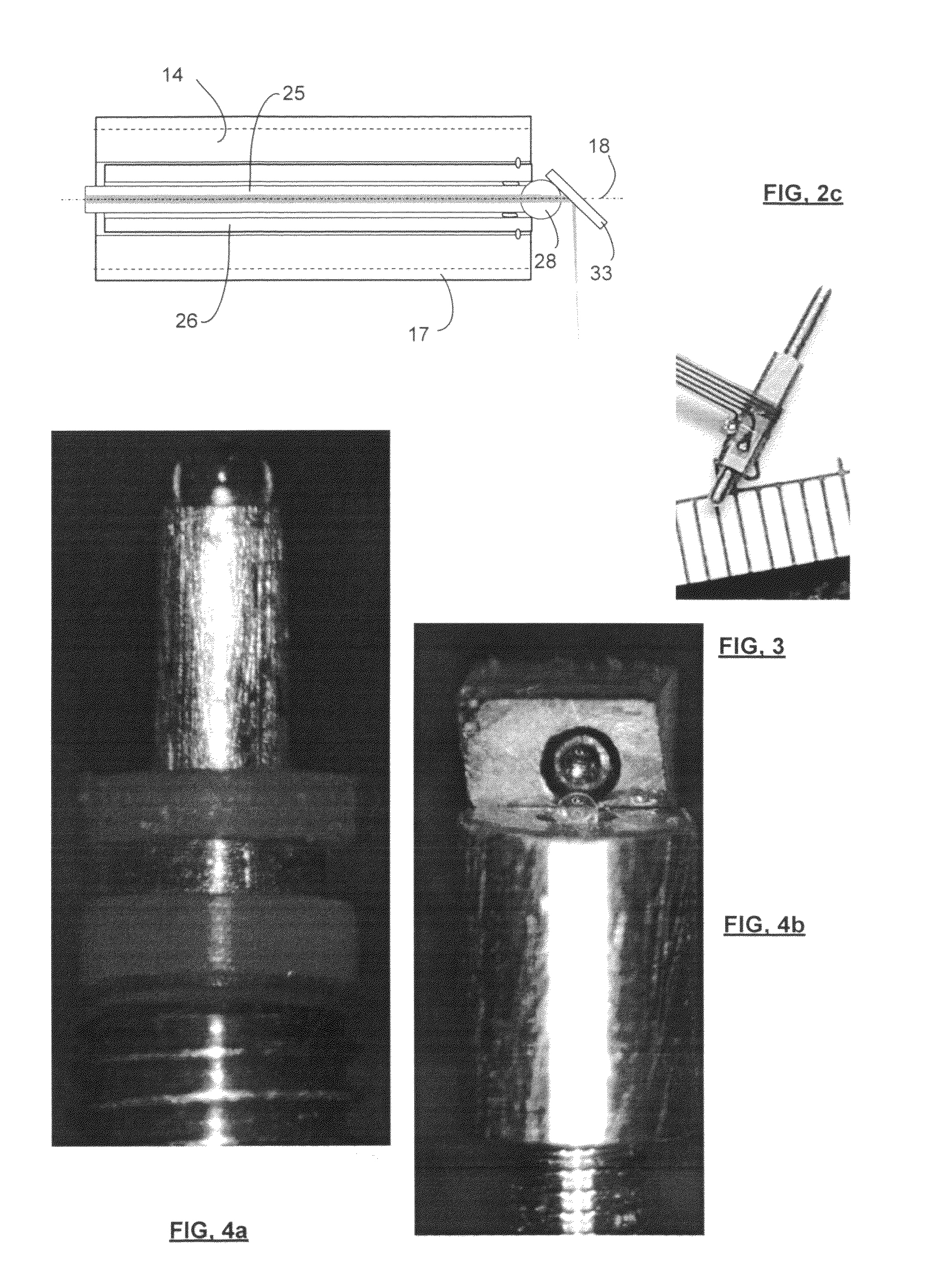
[0032]A prototype device has been produced. A commercially available miniature rotary motor, squiggle motor (outer diameter 1.8 mm, as shown in FIG. 3, shaft outer diameter 1.1 mm, thread pitch 0.16 mm) was obtained from New Scale Technologies (Victor, N.Y.). FIG. 3 is an image of the squiggle motor. Other squiggle motors, including some with smaller shaft OD (e.g., 1.5 mm are commercially available). A threaded shaft of the miniature motor was bored to produce a through hole along its centre axis with an inner diameter of 0.4 mm. This proved difficult, but the details are not provided here, as hollow shafts, even of these dimensions, can be provided in a variety of ways known in the art by forming techniques that are expected to be easier than boring an axial hole through a solid shaft as done in the present instance.

[0033]A fibre with a protective steel sheath was obtained from (SMF-130V, Prime Optical Fiber Corporation), having an OD of 0.125 mm. The fibre had a ball lens formed ...


PUM


Abstract

A scanning optical head for a catheter is locally controlled by a motor at an insertion end of the catheter uses a hollow motor through which a longitudinal optical path of the catheter passes. This permits the motor to be positioned between a control base of the catheter and avoids rotating the whole fiber, and therefore makes the beam scanning stable and accurate. In addition, because there is no coupling component, it also eliminates the light reflection between additional surfaces as well as varying fiber birefringence, which becomes a cause of noise when imaging the deep structure.

Description

FIELD OF THE INVENTION[0001]The present invention relates in general to optical catheters, and, in particular, to an optical catheter with a motorized rotary optical cap for 360° azimuthal scanning of the beam without occlusion of the beam, the catheter design being scalable to outer diameter sizes smaller than 2 mm.BACKGROUND OF THE INVENTION[0002]Optical catheters are increasingly used for a wide variety of optical diagnostic procedures and interventions. Accessing tissues via blood vessels, or other orifices, as opposed to by open surgery, reduces damage to the body, facilitating recovery. Generally the finer the catheter, the smaller the blood vessel it can enter. The present invention is particularly suited to providing catheters having small diameters and requiring reliable rotation.[0003]A reliable rotary fibre scanner is a critical part of optical coherence tomography (OCT) systems employed for medical imaging and diagnosis, particularly, to intravascular and cardiovascular ...

Claims


Application Information

Patent Timeline
Patent Type & Authority Patents(United States)
IPC IPC(8): G02B6/06G01B9/02A61B1/06
CPCA61B5/0062A61B5/0084A61B5/6852A61M25/0067A61M25/0113A61B1/00096A61B5/0066A61B5/0075
Inventor CHANG, SHOUDEMURDOCK, ERROLLFLUERARU, COSTELMAO, YOUXIN
Owner NAT RES COUNCIL OF CANADA
Why Eureka
Try Eureka