
Method for managing a memory apparatus, and associated memory apparatus thereof

a memory apparatus and management method technology, applied in the field of flash memory control, can solve problems such as inacceptable processing time, and achieve the effects of saving the time of building logical-to-physical, efficient management of all blocks, and improving performan

Active Publication Date: 2012-07-10
SILICON MOTION INC (TW)
View PDF11 Cites 3 Cited by
  • Summary
  • Abstract
  • Description
  • Claims
  • Application Information

AI Technical Summary

Benefits of technology

[0016]It is an advantage of the present invention that, in contrast to the related art, the present invention method and apparatus can greatly save the time of building logical-to-physical address linking table(s), such as the time of building a logical-to-physical page address linking table. Therefore, the present invention provides better performance than the related art.
[0017]It is another advantage of the present invention that the present invention method and apparatus can record the usage information during accessing the pages, and therefore can efficiently manage the usage of all blocks according the usage information. As a result, the arrangement of the spare region and the data region can be optimized.
[0018]These and other objectives of the present invention will no doubt become obvious to those of ordinary skill in the art after reading the following detailed description of the preferred embodiment that is illustrated in the various figures and drawings.

Problems solved by technology

If a block has 1024 pages, the time required for building the global page address linking table is 1024 times the time required for building the logical-to-physical block address linking table, i.e. 1024·x seconds, which is an unacceptable processing time since the processing speed is too slow.

Method used


Image

  • Method for managing a memory apparatus, and associated memory apparatus thereof
  • Method for managing a memory apparatus, and associated memory apparatus thereof
  • Method for managing a memory apparatus, and associated memory apparatus thereof

Examples


Embodiment Construction

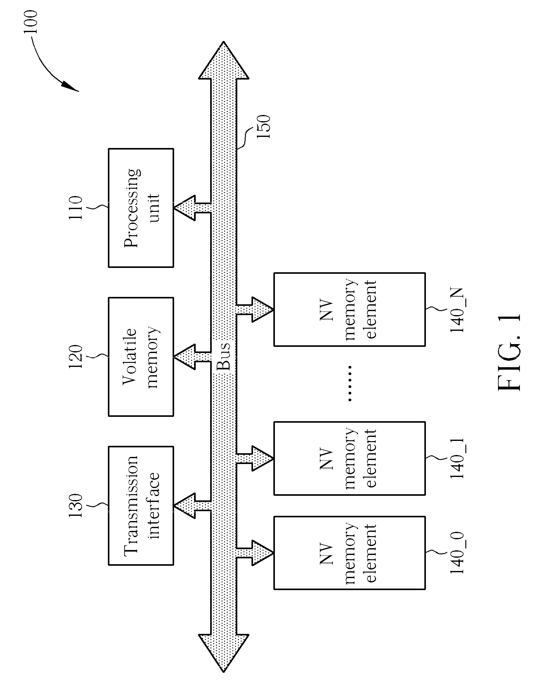
[0031]Please refer to FIG. 1, which illustrates a block diagram of a memory apparatus 100 according to a first embodiment of the invention. The memory apparatus 100 comprises a processing unit 110, a volatile memory 120, a transmission interface 130, a plurality of non-volatile (NV) memory elements 140_0, 140_1, . . . , and 140_N (e.g. flash chips), and a bus 150. Typically, a host (not shown in FIG. 1) can be arranged to access the memory apparatus 100 through the transmission interface 130 after the transmission interface 130 is coupled to the host. For example, the host can represent a personal computer such as a laptop computer or a desktop computer.

[0032]The processing unit 110 is arranged to manage the memory apparatus 100 according to a program code (not shown in FIG. 1) embedded in the processing unit 110 or received from outside the processing unit 110. For example, the program code can be a hardware code embedded in the processing unit 110, such as a ROM code. In another e...


PUM


Abstract

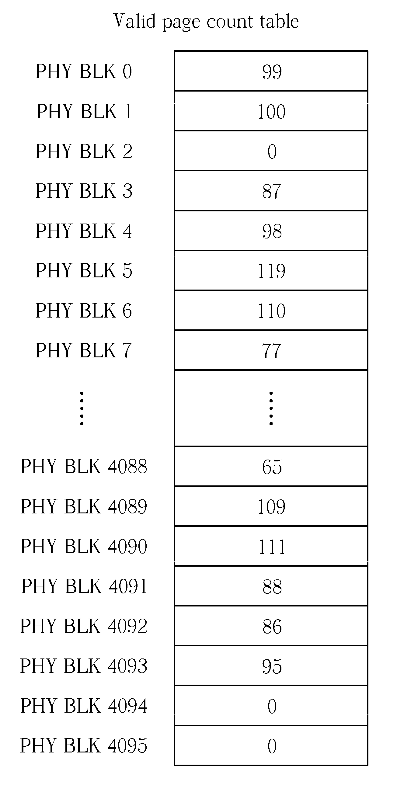
A method for managing a memory apparatus including at least one non-volatile (NV) memory element includes: recording usage information of at least one block during accessing pages of the block; and determining whether to erase a portion of the blocks according to the usage information. For example, the usage information includes a valid page count table for recording valid page counts of the blocks, respectively; and the ranking of a field of the valid page count table represents a physical block address, and the content of the field represents an associated valid page count. In another example, the usage information includes an invalid page count table for recording invalid page counts of the blocks, respectively; and the ranking of a field of the invalid page count table represents a physical block address, and the content of the field represents an associated invalid page count.

Description

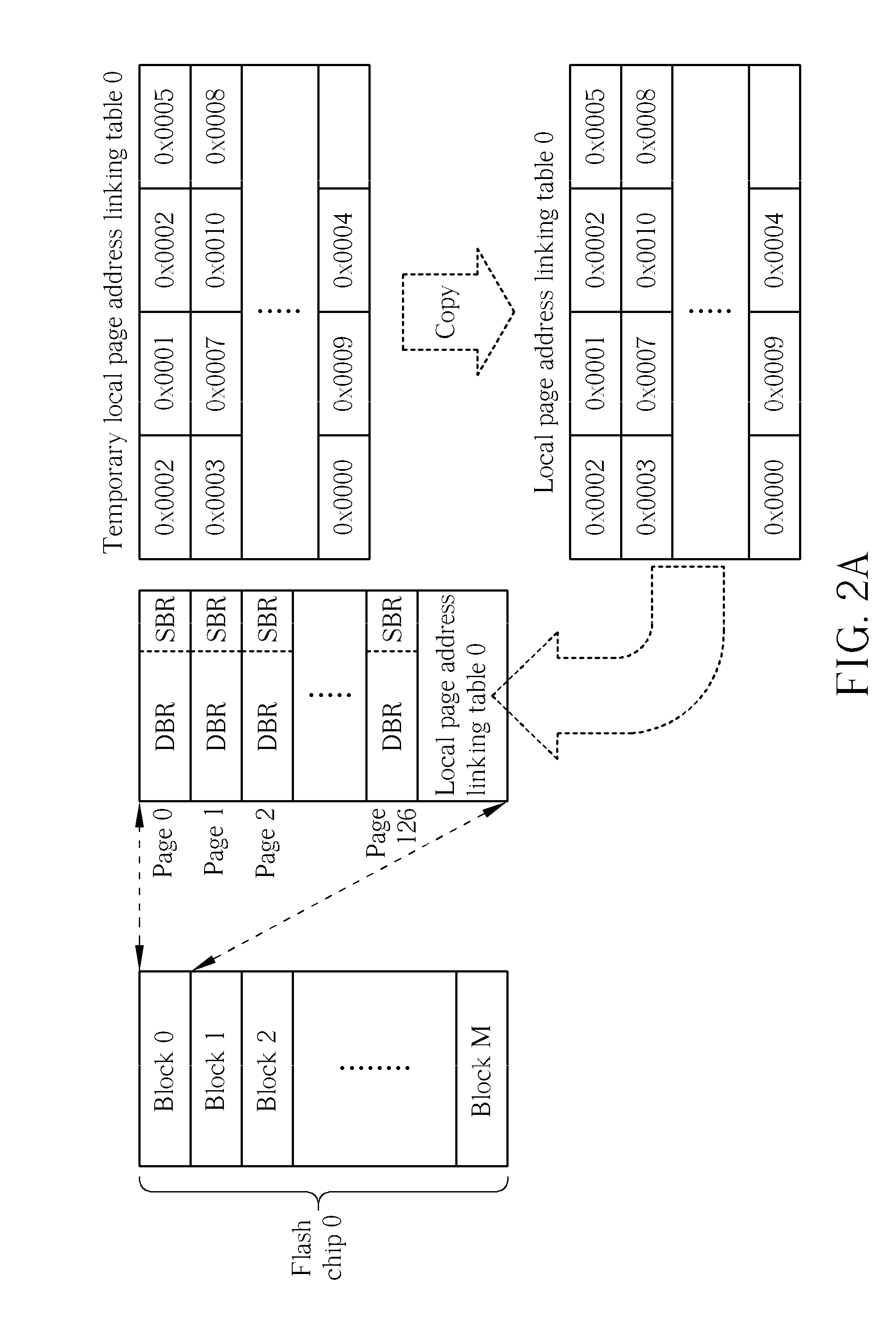
CROSS REFERENCE TO RELATED APPLICATIONS[0001]This application claims the benefit of U.S. Provisional Application No. 61 / 112,173, which was filed on Nov. 6, 2008, and is entitled “METHOD FOR BUILDING A LOGICAL-TO-PHYSICAL ADDRESS LINKING TABLE OF A MEMORY APPARATUS”. This application further claims the benefit of U.S. Provisional Application No. 61 / 140,850, which was filed on Dec. 24, 2008, and entitled “METHOD FOR MANAGING AND ACCESSING A STORAGE APPARATUS”.BACKGROUND OF THE INVENTION[0002]1. Field of the Invention[0003]The present invention relates to flash memory control, and more particularly, to a method for managing a memory apparatus, and an associated memory apparatus thereof.[0004]2. Description of the Prior Art[0005]While a host is accessing a memory apparatus (e.g. a solid state drive, SSD), the host typically sends an accessing command and at least a corresponding logical address to the memory apparatus. The controller of the memory apparatus receives the logical address ...

Claims


Application Information

Patent Timeline
Patent Type & Authority Patents(United States)
IPC IPC(8): G06F12/00
CPCG06F12/0246G06F2212/7208G06F2212/7207G06F12/1009G06F2212/7209
Inventor LEE, CHUN-KUNLIN, TSAI-CHENG
Owner SILICON MOTION INC (TW)
Learn More