Crimp terminal, terminal-provided wire, and manufacturing method thereof

a technology of crimp terminal and terminal, which is applied in the direction of line/current collector details, connection formation by deformation, and permanent deformation connections, etc., can solve the problems of difficult to set the crimp height of the conductor barrel, the difficulty of using these materials, and the difficulty of crimp height setting, etc., to achieve the effect of ensuring mechanical strength, reducing contact resistance, and sufficient mechanical strength

Inactive Publication Date: 2012-07-17
AUTONETWORKS TECH LTD +2
View PDF19 Cites 50 Cited by
  • Summary
  • Abstract
  • Description
  • Claims
  • Application Information

AI Technical Summary

Benefits of technology

[0008]It is an object of the present invention to provide a technique which enables both of ensuring mechanical strength in a terminal-provided wire and lowering contact resistance between the wire and the crimp terminal to be established, while not greatly varying a crimp height of a crimp terminal onto the wire in an axial direction.
[0012]According to the crimp terminal and the terminal-provided wire, the second inner surface, which is a part of the inner surface of the conductor barrel of the crimp terminal and closely contacts the tip end side part of the conductor, inwardly projects beyond the second surface which closely contacts the base side part of the conductor; this makes it possible to establish both of ensuring the sufficient mechanical strength in the terminal-provided wire and lowering contact resistance, without greatly varying the crimp height of the conductor barrel in the axial direction.
[0013]The present invention further provides a method of manufacturing a terminal-provided wire comprising a wire having an end in which a conductor is exposed and a crimp terminal crimped to the end, the method including: a terminal forming step of forming the above-mentioned crimp terminal from a metal plate; and a crimping step of crimping the conductor barrel of the crimp terminal onto the conductor by setting the conductor in the end of the wire onto the wire crimp portion of the crimp terminal and bending the conductor barrel such that the conductor barrel holds the conductor on the end of the wire. This method makes it possible to manufacture a terminal-provided wire given both of ensured mechanical strength and lowered contact resistance simply by previously forming the crimp terminal having the conductor barrel and thereafter crimping the conductor barrel of the crimp terminal to the conductor on the end of the wire.

Problems solved by technology

This crimping technique, however, involves a difficulty of setting a crimp height of the conductor barrel.
Particularly in recent years, there is conducted a study on the use of aluminum or aluminum alloy as the material of the conductor included in the wire, the use of these materials involving extremely difficulty of setting the crimp height.
This means that it is not easy to set and manage the crimp height of a terminal-provided wire including a conductor made of aluminum or an aluminum alloy so as to satisfy both of mechanical strength and contact resistance requirements.
The larger the step, the more likely damage such as cracks is given to the terminal.
Furthermore, it is practically difficult to manufacture a terminal-provided wire including such a large step by use of a single crimping die; in actuality, separate crimping dies must be used for the different crimp height parts, management of which involves extreme troublesome.Patent Document 1: Japanese Patent Application Publication No. 2005-50736

Method used


Image

  • Crimp terminal, terminal-provided wire, and manufacturing method thereof
  • Crimp terminal, terminal-provided wire, and manufacturing method thereof
  • Crimp terminal, terminal-provided wire, and manufacturing method thereof

Examples


first embodiment

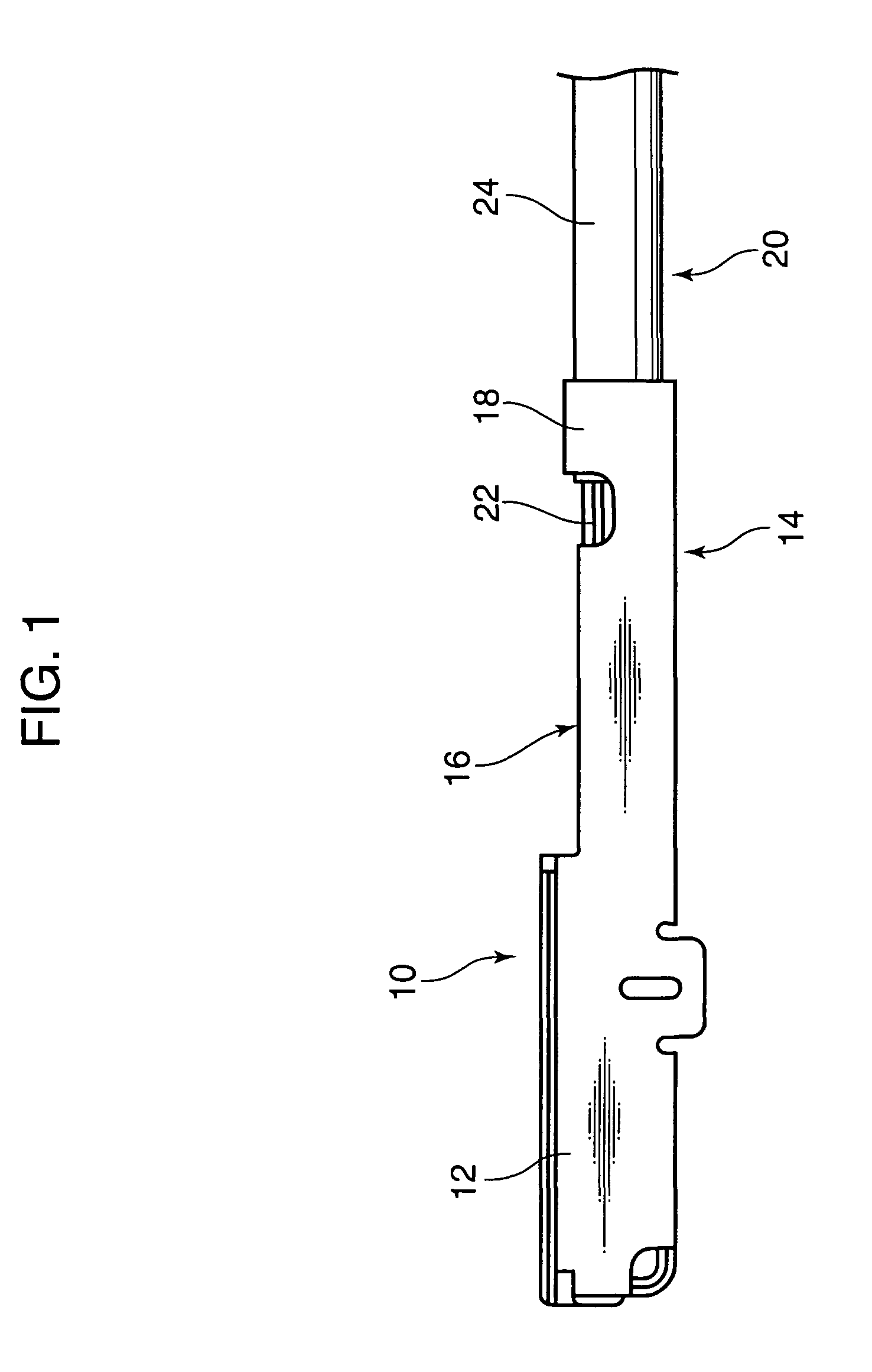
[0039]FIG. 1 shows a terminal-provided wire manufactured according to the present invention. This terminal-provided wire includes a wire 20 and a crimp terminal 10. The wire 20 is formed of a conductor 22 and an insulating covering 24 covering the conductor 22 from a radial outer side. There is removed a part of the insulation covering 24 in an end of the wire 20 to partially expose the conductor 22. Onto this end of the wire 20, the crimp terminal 10 is crimped.

[0040]The conductor 22 is not limited to its material: various materials in addition to typically employed copper and copper alloy are permitted to be used. However, the present invention is particularly effective in the case where the conductor is formed from a material, such as aluminum or aluminum alloy, whose surface tends to be formed with an oxide film causing a requirement of a high degree of compression during the crimping.

[0041]The terminal-provided wire is manufactured through the following terminal forming process...

second embodiment

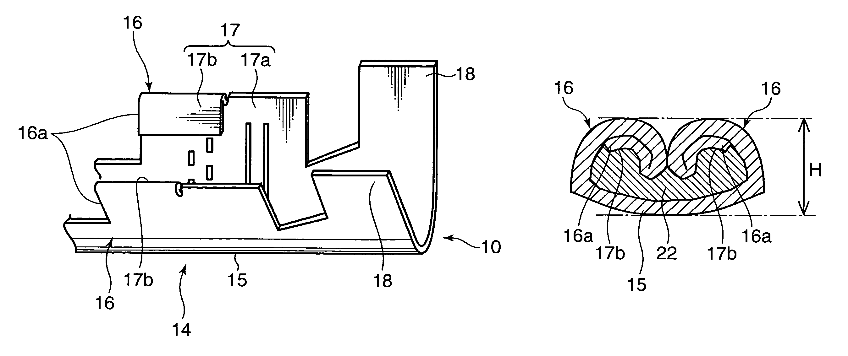
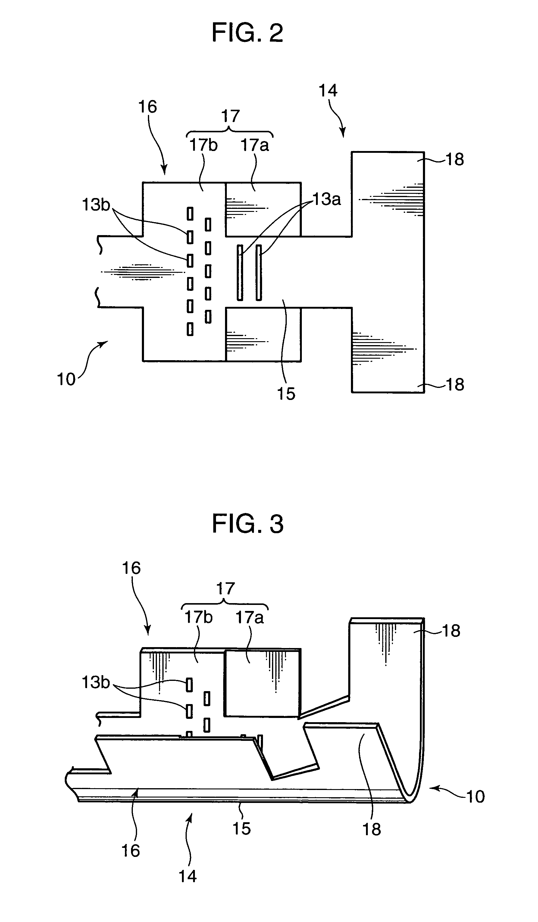
[0058]The aforementioned height difference may be applied not only to the inner surface of the conductor barrel 16 but also to the inner surface of the basal portion 15. For example, as a second embodiment shown in FIGS. 8 and 9, the inner surface of the basal portion 15 sandwiched between the two first inner surfaces 17a may be recessed similarly to the first inner surfaces 17a. In this case, the first recessed portions 13a may be formed, as shown in the drawings, continuously in a region across the inner surface of the basal portion 15 and the first inner surfaces 17a on both sides thereof.

third embodiment

[0059]Furthermore, the inner surface of the conductor barrel according to the present invention need not absolutely include a step as described above, permitted to be a tapered surface, like an inner surface 17 shown in FIGS. 10 and 11 as a third embodiment, having an inward projection which gradually increases with closing to the tip end side part of the conductor 22. Also the inner surface 17 having such a shape can give a difference in compression ratio between the tip end side part and the base side part of the conductor 22, and further vary the compression ratio of the conductor 22 smoothly in the axial direction. As other example, radial positions of the inner surface 17 may be given variations in a shape of including three or more steps.

[0060]The first inner surface 17a and the second inner surface 17b having the above-mentioned height difference can be formed also by inwardly folding back an appropriate peripheral edge part of the metal plate constituting the conductor barre...


PUM

PropertyMeasurementUnit
compression ratioaaaaaaaaaa
shapeaaaaaaaaaa
widthaaaaaaaaaa

Abstract

Provided is a technique of ensuring mechanical strength in a terminal-provided wire and lowering contact resistance between the wire and the crimp terminal, without greatly varying a crimp height of a crimp terminal onto the wire in an axial direction. A crimp terminal according to the invention includes a conductor barrel which is crimped to a conductor of a wire. The conductor barrel has an inner surface which closely contacts the conductor by bending. The inner surface has such a shape a surface thereof which closely contacts a tip end side part of the conductor inwardly projects beyond a surface thereof which closely contacts a base side part of the conductor, thus performing a higher compression of the tip end side part of the conductor than that of the base side part thereof by the bending.

Description

FIELD OF THE INVENTION[0001]The present invention relates to a crimp terminal which is crimped to an end of a wire provided for an automobile or the like, a terminal-provided wire including the crimp terminal, and a manufacturing method thereof.BACKGROUND ART[0002]To attach a terminal to an end of an insulated wire, there is conventionally often used a crimping technique. The crimping is performed by caulking a conductor barrel formed in advance on the terminal to the end of a conductor of the insulated wire by use of a die.[0003]This crimping technique, however, involves a difficulty of setting a crimp height of the conductor barrel. A low crimp height has a merit of lowering contact resistance between the conductor barrel and the conductor, while causing a demerit of decreasing mechanical strength, in particular tensile strength against an impact load (more specifically, the strength by which the crimp terminal holds the wire), because of a high reduction rate of the conductor sec...

Claims


Application Information

Patent Timeline
Patent Type & Authority Patents(United States)
IPC IPC(8): H01R4/18
CPCH01R4/185H01R4/188Y10T29/49218H01R43/048
Inventor ONO, JUNICHIHIRAI, HIROKITANAKA, TETSUJISHIMODA, HIROKIOTSUKA, TAKUJIOGIHARA, SHIGERUITO, AKIRA
Owner AUTONETWORKS TECH LTD
Why Eureka
Try Eureka