Crimp terminal, terminal-equipped electric wire with the crimp terminal, and methods for producing them

a technology of crimp terminal and electric wire, which is applied in the direction of line/current collector details, contact member coupling, and connection effected by permanent deformation, etc. it can solve the problems of easy breakage of tin oxide film and little effect on contact resistance, so as to reduce contact resistance and allow contact resistance to be maintained , good adhesion

Inactive Publication Date: 2013-07-30
AUTONETWORKS TECH LTD +2
View PDF31 Cites 9 Cited by
  • Summary
  • Abstract
  • Description
  • Claims
  • Application Information

AI Technical Summary

Benefits of technology

[0009]In view of the above circumstances, it is an object of the present invention to provide a crimp terminal capable of achieving both of ensuring mechanical strength of an terminal-equipped electric wire having the crimp terminal and reducing a contact resistance between an electric wire and the crimp terminal without giving a significant height difference to a electric-wire crimp section of the crimp terminal, and to provide a terminal-equipped electric wire having the crimp terminal, and methods for producing them.
[0012]However, it has been found that the tin-plating layer, while having the above advantage, could be a factor hindering a reduction in contact resistance between the crimp terminal and a conductor in an end portion of an electric wire onto which the crimp terminal is crimped. This would be because the tin-plating layer has a characteristic of being more slippery (than copper or a copper alloy) against the conductor of the electric wire, and the slip hinders adhesion between the crimp terminal and the conductor by press contact with each other to inhibit a reduction in the contact resistance based on the adhesion.
[0014]In the electric contact section of this crimp terminal, the existence of the tin-plating layer in the electric contact surface region enables adequate electric contact with the counterpart terminal to be ensured, as with a conventional crimp terminal, while, in the electric-wire crimp section, the smaller thickness of the tin-plating layer in the crimp surface region than that in the electric contact surface region makes it possible to provide good adhesion between the crimp surface region and the conductor of the electric wire to reduce a contact resistance therebetween, as compared with a conventional crimp terminal where the thickness of the tin-plating layer in the crimp surface region is equal to that in the electric contact surface region. In short, the contact resistance is allowed to be maintained at a low level not involving an increase in a degree of deformation for crimping of the electric-wire crimp section (for example, without lowering a crimp height of a conductor barrel).

Problems solved by technology

Although the tin-plating layer also has a surface where a tin oxide film is formed, this tin oxide film is likely to break easily, as compared with the copper oxide film, thus having little effect on the contact resistance.

Method used


Image

  • Crimp terminal, terminal-equipped electric wire with the crimp terminal, and methods for producing them
  • Crimp terminal, terminal-equipped electric wire with the crimp terminal, and methods for producing them
  • Crimp terminal, terminal-equipped electric wire with the crimp terminal, and methods for producing them

Examples


examples

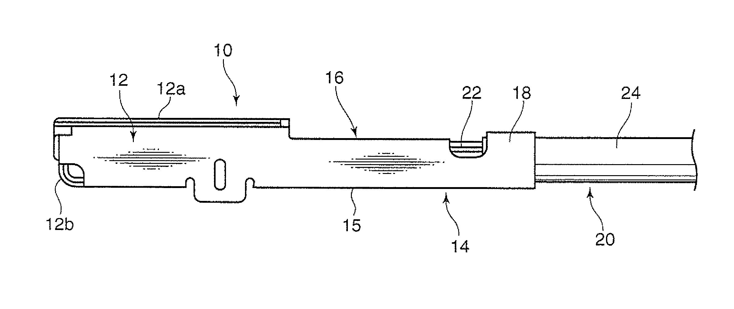
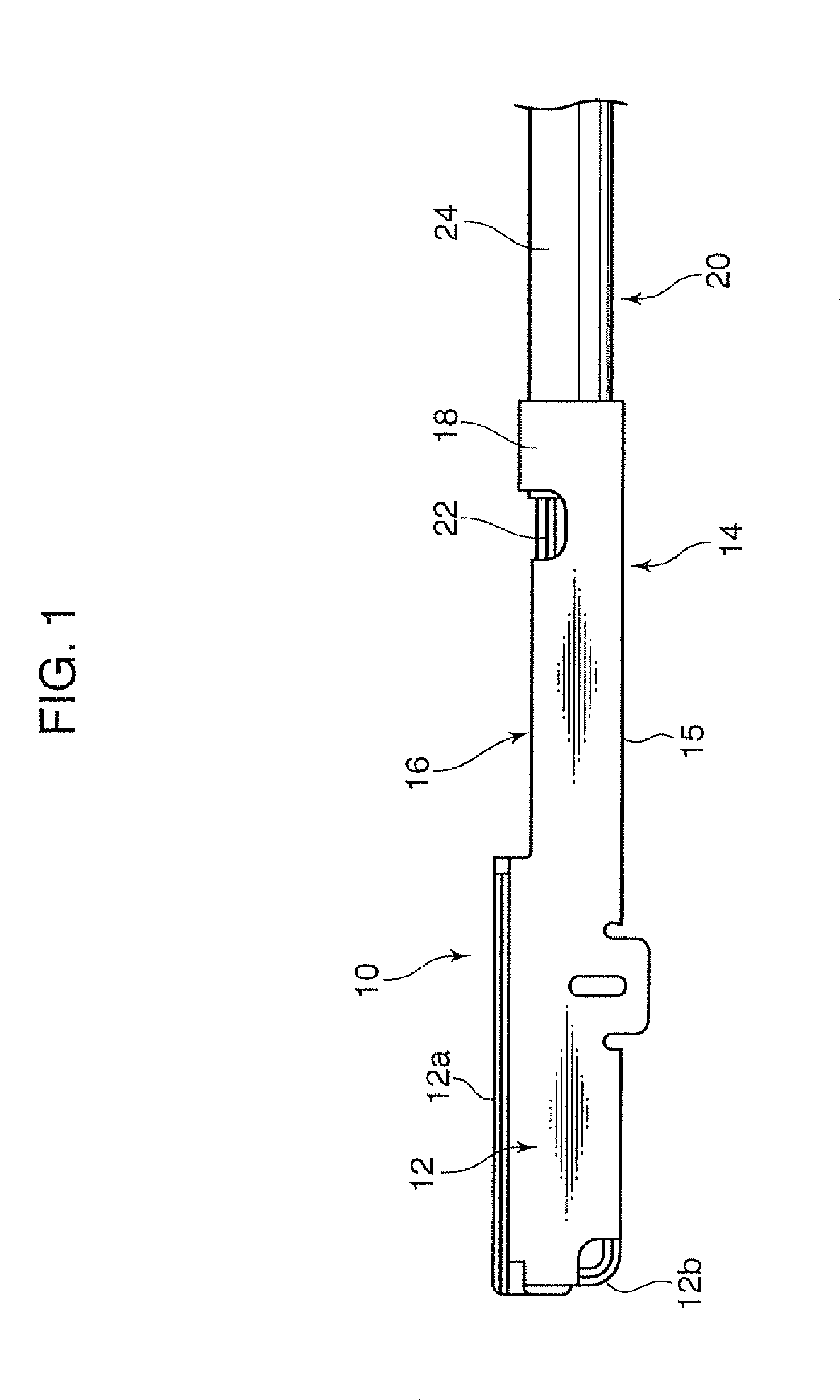
[0053]As for an inventive example and a comparative example, there was carried out a test for measuring a fixed strength and a contact resistance. The comparative example provides a crimp terminal, which has a structure equivalent to that of the crimp terminal 10 shown in FIG. 1, formed of a metal plate constituted by a plate body made of brass and a tin-plating layer laminated on the surface of the plate body with a thickness of 0.8 to 1.5 μm. Differently, the inventive example provides a crimp terminal where the thickness of the tin-plating layer in the crimp surface region was reduced to about 0.3 μm by a local heat treatment at 150° C.

[0054]FIGS. 7 and 8 show respective measurement results of the comparative example and the inventive example. These show respective graphs, each of which includes a horizontal axis representing a clamp height (crimp height) of the conductor barrels, and vertical axes indicate a fixed strength (which is a force by which the conductor barrels are fix...


PUM

PropertyMeasurementUnit
thicknessaaaaaaaaaa
thicknessaaaaaaaaaa
thicknessaaaaaaaaaa

Abstract

Provided is a crimp terminal designed to be crimped onto an end portion of an electric wire to form a terminal-equipped electric wire, achieving both of ensuring mechanical strength of the terminal-equipped electric wire and reducing a contact resistance between the electric wire and the crimp terminal. The crimp terminal comprises an electric contact section and an electric-wire crimp section to be crimped onto a conductor in the end portion of the electric wire, the crimp terminal being formed of a metal plate which has a copper-containing plate body and a tin-plating layer covering a surface of the plate body. In the crimp terminal, the tin-plating layer has a smaller thickness in a crimp surface region where the electric-wire crimp section is to make contact with the end portion of the electric wire is less than that in an electrical contact surface region where the electric contact section is to make contact with a counterpart terminal.

Description

BACKGROUND OF THE INVENTION[0001]1. Field of the Invention[0002]The present invention relates to a crimp terminal adapted to be crimped onto an end portion of an electric wire to be wired in an automobile or the like, a terminal-equipped electric wire having the crimp terminal, and production methods for them.[0003]2. Description of the Related Art[0004]As means for attachment of a terminal to an end portion of an insulated electric wire, has been widely used a crimp technique as disclosed, for example, in Patent Document 1: JP 2005-50736A. The crimp is performed by crimping an electric-wire crimp section (e.g., conductor barrel) preliminarily formed in the terminal onto an end portion of a conductor of the insulated electric wire.[0005]However, the above crimp technique involves difficulty in setting a degree of deformation of the electric-wire crimp section. For example, in the case where the electric-wire crimp section is a conductor barrel, it is difficult to set a crimp height ...

Claims


Application Information

Patent Timeline
Patent Type & Authority Patents(United States)
IPC IPC(8): H01R4/10
CPCH01R4/185H01R13/03H01R43/16Y10T29/49218Y10T29/49224
Inventor ONO, JUNICHIHIRAI, HIROKITANAKA, TETSUJISHIMODA, HIROKIOTSUKA, TAKUJI
Owner AUTONETWORKS TECH LTD
Why Eureka
Try Eureka