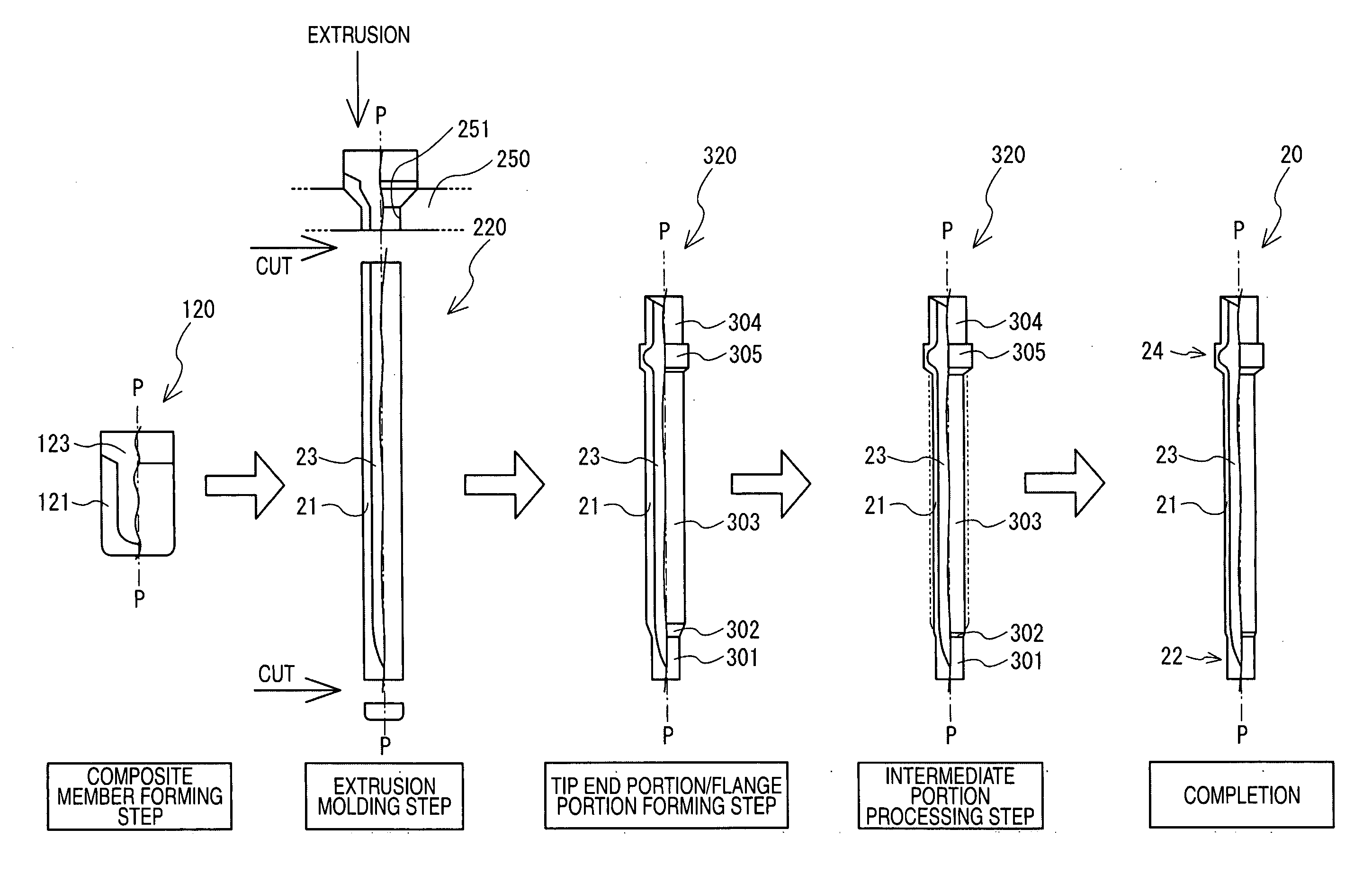
[0020]In the method of producing a spark plug of the invention of claim 1, the first intermediate member is produced by, in the first step, applying the plastic working process on the blank member which is configured by joining the material that will be used as the core portion, to the material that will be used as the cover portion. Usually, this process is performed by
extrusion molding. By the step, the first intermediate member can be finished into a form in which the core portion is covered by the cover portion. By the process, the core portion and the cover portion can be uniformly extended, and hence the thickness of the cover portion can be set to a substantially uniform state. When the second intermediate member having the
flange portion, the tip end portion, and the intermediate portion is produced in the second step, the flange portion and the tip end portion are formed by applying the plastic working process on the first intermediate member in which the cover portion covers the core portion as described above, and hence the thickness of the cover portion in the intermediate portion can be maintained to the substantially uniform state. When, in this state, the surface of the cover portion of the intermediate portion of the second intermediate member is
cut or polished in the third step, only the thickness of the cover portion of the middle trunk portion can be reduced without changing the outer diameter of the core portion covered by the cover portion. Namely, the reduction of the diameter of the produced center electrode can be realized by reducing only the thickness of the cover portion. As described above, according to the invention, when the reduction of the diameter of the intermediate portion is performed in the third step, the rate of the core portion is relatively increased. Therefore, the outer diameter of the center electrode can be reduced while maintaining the heat dissipation property of the center electrode. The outer diameter of the tip end portion may be smaller than that of the intermediate portion, or alternatively may be equal thereto.
[0021]In the
cutting or
polishing of the cover portion in the third step, as the thickness of the cover portion is further reduced, the
mechanical strength of the intermediate portion is further weakened. When the cover portion of the intermediate portion of the second intermediate member has a reduced thickness, consequently, there is the possibility that the intermediate portion may be broken because the portion receives a
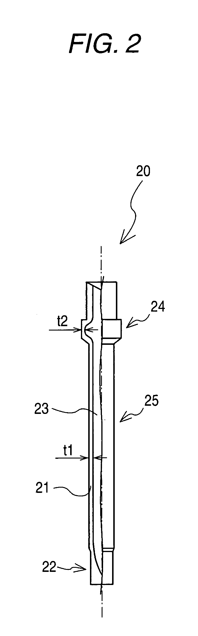
resistance force from a
cutting blade or a whetstone in the third step. As the invention of claim 2, therefore, the thicknesses of the cover portions in the axial center of the intermediate portion of the second intermediate member and the flange portion are set to 0.3 to 0.4 mm. According to the configuration, the
mechanical strength of the intermediate portion of the second intermediate member before performing the third step can be sufficiently ensured, and hence the breaking of the intermediate portion in the third step can be suppressed.
[0022]In the
cutting or
polishing of the cover portion in the third step, the
mechanical strength of the intermediate portion is further weakened as the thickness of the cover portion is further reduced. Consequently, there is the possibility that the intermediate portion may be broken because the portion receives a
resistance force from a cutting blade or a whetstone. When the
hardness of the cover portion has a Vickers
hardness of 270 Hv or more as the invention of claim 3, however, a sufficient mechanical strength can be maintained even in a reduced thickness of the cover portion, and breakage can be prevented from occurring.
[0023]According to the method of producing a spark plug of claim 4, in the third step, the surface of the cover portion of the intermediate portion of second intermediate member is
cut or polished so that the ratio of the thickness of the cover portion of the middle trunk portion to that of the cover portion of the flange portion is 0.8 or less. In the thus-produced spark plug, therefore, the rate of the core member in the middle trunk portion is relatively large, and hence the heat dissipation property of the center electrode can be ensured even when the middle trunk portion of the center electrode has a reduced outer diameter.
[0024]According to the method of producing a spark plug of claim 5, in the third step, the surface of the cover portion of the intermediate portion of second intermediate member is cut or polished so that the difference between the thickness of the cover portion of the flange portion and that of the cover portion of the middle trunk portion is 0.05 mm or more. Therefore, the thus-produced spark plug can sufficiently exhibit the heat dissipation property of the center electrode.
[0025]In order to further improve the heat dissipation property of the center electrode, the rate of the intermediate portion in which the cover portion is cut or polished in the third step, with respect to the second intermediate member may be increased. When, as in claim 6, the intermediate portion has a length which is equal to one half or more of the whole length of the second intermediate member, the cover portion having a length which is one half or more of the whole length of the second intermediate member is cut or polished in the third step. In the thus produced center electrode, therefore, a portion having a length which is one half or more of the whole length of the center electrode is formed as the middle trunk portion, and it is possible to further improve the heat dissipation property of the center electrode.

