High slot utilization systems for electric machines

a technology of high slot utilization and electric machines, which is applied in the direction of windings, dynamo-electric components, magnetic circuit shapes/forms/construction, etc., can solve the problems of not being able to put a form wound coil of non-rectangular layers, the best design of rectangular slots, etc., and achieve the best use of magnetic materials, high slot utilization, and highest fill factor

Inactive Publication Date: 2009-06-23
UT BATTELLE LLC
View PDF19 Cites 9 Cited by
  • Summary
  • Abstract
  • Description
  • Claims
  • Application Information

AI Technical Summary

Benefits of technology

[0005]Two new High Slot Utilization (HSU) Systems for electric machines are introduced. Both systems enable the use of form wound coils that have the highest fill factor and the best use of magnetic materials. The epoxy / resin / curing treatment ensures the mechanical strength of the assembly of teeth, core, and coils. In addition, the first HSU system allows the coil layers to be moved inside the slots for the assembly purpose. After the coils are properly located, the plugged-in teeth are inserted into the space between the coil layers. Various methods can be used to secure the plugged-in teeth. The second system uses the slided-in teeth instead of the plugged-in teeth. The form wound coils are put into the slots by entering the bottom of slots.
[0006]The power density of the electric machine that uses either system can reach to its highest limit. The productivity can be increased because the preformed coils can simply be put together without going through the very small slot openings.

Problems solved by technology

The problem associated with the traditional form wound electric machine is that a rectangular slot may not be the best design.
The existing technology cannot put a form wound coil of this non-rectangular layers into a slot of a stator lamination stack with many distributed slots, because the big lower layer of the coil cannot go through the small opening of the slot.

Method used


Image

  • High slot utilization systems for electric machines
  • High slot utilization systems for electric machines
  • High slot utilization systems for electric machines

Examples


Embodiment Construction

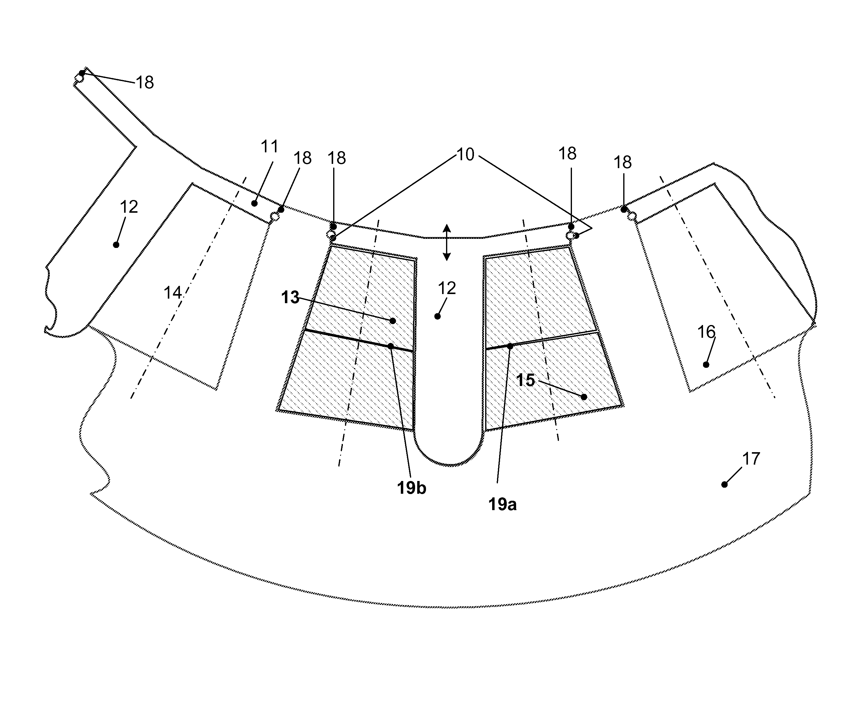
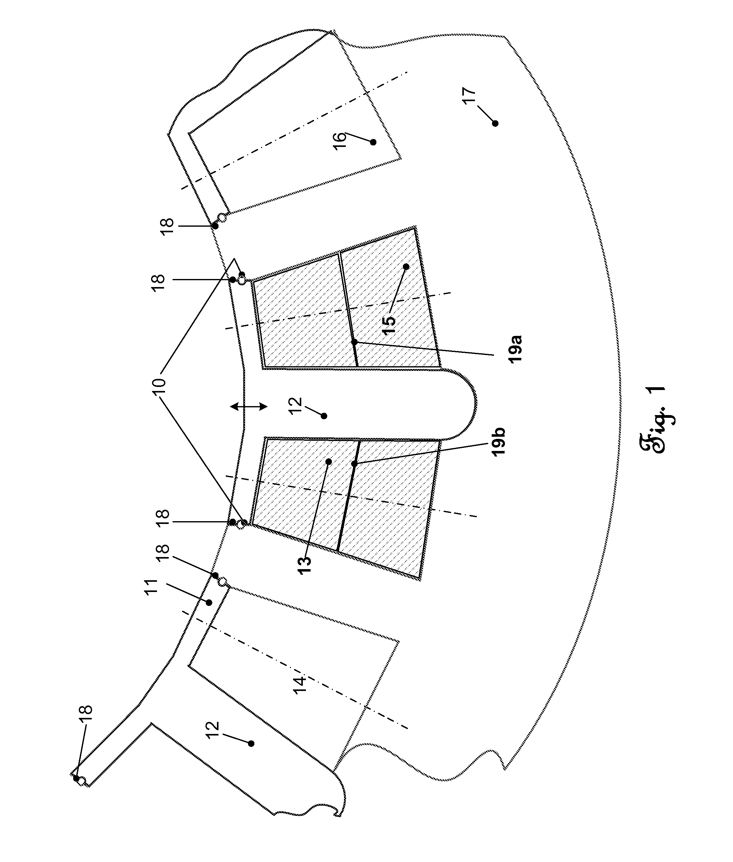
[0015]The First High Slot Utilization (HSU) System, as shown in FIG. 1, explains the first HSU system through an example of this invention. Each slot 16 of the stator punching 17 accommodates a first preformed wound coil 19a and second preformed wound coil 19b, each first and second coil having and upper layer 13 and a lower layer 15. These layers of coils are preformed before putting into the slots. A highest fill factor can be achieved due to the nature of preformed coils 14. FIG. 1 shows that every other tooth is a plugged-in tooth 12. When the plugged-in tooth 12 is absent, the large opening enables the coils' entering the slots and moving inside the slot. This feature will be shown further in the additional figures. The circular bottom of the plugged-in tooth 12 provides a larger interfacing area for the magnetic flux to go between the tooth and the stator core. The top of the plugged-in tooth consists of two magnetically saturable extensions 11 that can limit the slot leakage ...


PUM


Abstract

Two new High Slot Utilization (HSU) Systems for electric machines enable the use of form wound coils that have the highest fill factor and the best use of magnetic materials. The epoxy / resin / curing treatment ensures the mechanical strength of the assembly of teeth, core, and coils. In addition, the first HSU system allows the coil layers to be moved inside the slots for the assembly purpose. The second system uses the slided-in teeth instead of the plugged-in teeth. The power density of the electric machine that uses either system can reach its highest limit.

Description

CROSS-REFERENCE TO RELATED APPLICATIONS[0001]This application claims priority to U.S. Provisional Patent Application 60 / 596,541 filed Oct. 3, 2005, and is herein incorporated by reference.STATEMENT REGARDING FEDERALLY SPONSORED RESEARCH[0002]This invention was made with United States Government support under Contract No. DE-AC05-000R22725 between the United States Department of Energy and U.T. Battelle, LLC. The United States Government has certain rights in this invention.BACKGROUND OF THE INVENTION[0003]Preformed coils offer the highest numbers of wires that can be packed inside a slot. The commonly known “form wound” coils refer to the coils with their conductors arranged in a rectangulae-shape for a rectangular coil layer. The coil layer is put into a rectangular slot in the stator core. The problem associated with the traditional form wound electric machine is that a rectangular slot may not be the best design. In fact, most of the small and medium size electric machines genera...

Claims


Application Information

Patent Timeline
Patent Type & Authority Patents(United States)
IPC IPC(8): H02K1/16H02K1/18
CPCH02K1/165H02K3/493H02K15/024H02K15/066H02K3/12H02K3/28
Inventor HSU, JOHN S
Owner UT BATTELLE LLC
Why Eureka
Try Eureka