
Radio terminal, radio base station and radio communication method

a radio terminal and radio communication technology, applied in the direction of wireless network protocols, electrical equipment, wireless commuication services, etc., can solve the problem that the adaptive communication control cannot be started

Active Publication Date: 2012-07-17
KYOCERA CORP
View PDF5 Cites 2 Cited by
  • Summary
  • Abstract
  • Description
  • Claims
  • Application Information

AI Technical Summary

Benefits of technology

The present invention provides a solution for measuring the quality of radio communication between a radio terminal and a radio base station during handover. The solution involves transmitting and receiving a lower layer message using a protocol of a layer lower than an IP layer to and from the radio terminal before the radio terminal acquires a new IP address. The quality measurement unit measures the radio communication quality using the lower layer message and the network communication quality between the radio terminal and the radio base station. This allows for the measurement of the radio communication quality prior to acquiring a new IP address, even in a case where the radio terminal is assigned the new IP address at the time of handover. The solution also includes a link establishing unit for establishing a radio link with the radio base station and a protocol for transmitting and receiving the lower layer message. The invention improves the efficiency and reliability of handover procedures in radio communication networks.

Problems solved by technology

Accordingly, when a radio terminal is assigned a new IP address at the time of handover, the following problem occurs.
This leads to a problem that the adaptive communication control cannot be started until the radio terminal acquires the new IP address.

Method used


Image

  • Radio terminal, radio base station and radio communication method
  • Radio terminal, radio base station and radio communication method
  • Radio terminal, radio base station and radio communication method

Examples


first embodiment

[First Embodiment]

[0044]In the first embodiment, descriptions will be given as follows: (1) schematic configuration of communication system, (2) detailed configuration of communication system, (3) detailed operation of communication system, (4) details of messages and (5) effects and advantages.

[0045](1) Schematic Configuration of Communication System

[0046]Firstly, descriptions will be given of (1.1) overall configuration of communication system and (1.2) schematic configurations of radio terminal, radio base station and CN.

[0047](1.1) Overall Configuration of Communication System

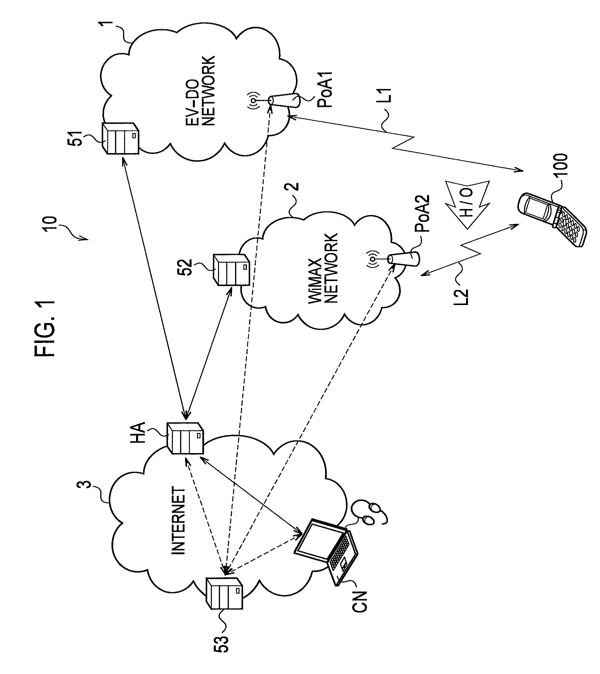
[0048]FIG. 1 is an overall configuration diagram of a communication system 10 according to the first embodiment.

[0049]A radio terminal 100 shown in FIG. 1 is configured to be connectable to multiple radio communication networks of different radio communication schemes (configurations of physical layers or link layers). The radio terminal 100 is a mobile terminal (Mobile Node or Mobile Router). In the first ...

second embodiment

[Second Embodiment]

[0144]In the following second and third embodiments, descriptions will be given of a case where an MIHF is not built into the CN and the home agent HA, so that a network communication quality cannot be measured by using the 802.21 framework. Note that, in the following second and third embodiments, descriptions will be given of points different from the first embodiment, and descriptions that overlap those of the first embodiment will be omitted.

[0145]FIG. 9 is a flowchart showing an operation of a communication system according to the second embodiment. In the flowchart shown in FIG. 9, only a radio communication quality is measured, and a network communication quality is not measured.

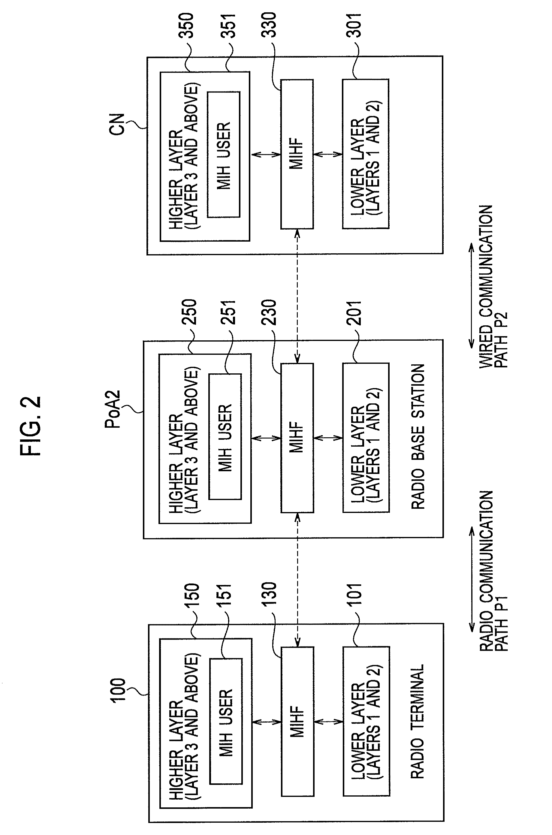
[0146]Specifically, in steps S217 and S219, the MIHF 130 of the radio terminal 100 and the MIHF 230 of the radio base station PoA2 transmit and receive Link_QoS_Parameters_Measure.request requesting measurement of a radio communication quality and Link_QoS_Parameters_Measure.confirm...

third embodiment

[Third Embodiment]

[0152]In the third embodiment, when not being able to be measured by using the 802.21 framework, a network communication quality is measured by using an ICMP packet, which is a type of an IP packet. FIG. 10 is a flowchart showing an operation of a communication system according to the third embodiment.

[0153]In step S317, the MIHF 230 of the radio base station PoA2, which has received a request for measurement of a network communication quality from the MIHF 130 of the radio terminal 100, requests the MIH user 251 of the radio base station PoA2 to measure the network communication quality between the radio base station PoA2 and the CN. In addition, in step S318, the MIHF 230 requests the MIHF 330 of the CN to measure the network communication quality between the CN and the radio base station PoA2.

[0154]The MIHF 330 of the CN having received the request for measurement requests the MIH user 351 of the CN to measure the network communication quality between the CN and...


PUM


Abstract

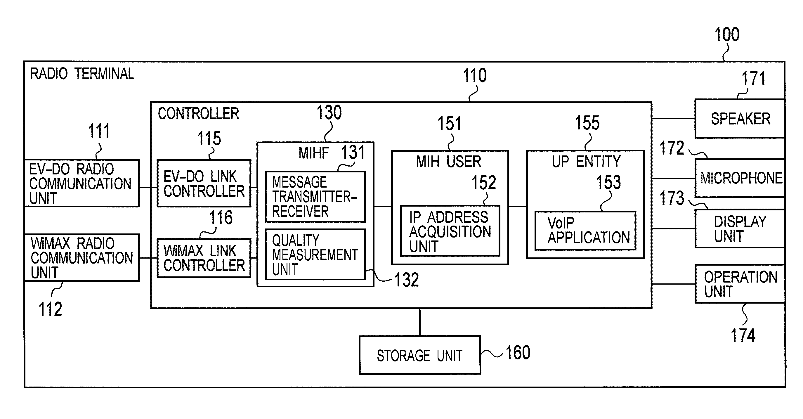
Disclosed is a radio terminal including: a message transmitter-receiver configured to transmit and receive an IEEE 802.21 message using a protocol of a layer lower than an IP layer to and from a target radio base station for handover before an IP address acquisition unit acquires a new IP address; and a quality measurement unit configured to measure a radio communication quality including at least one of transmission delay and jitter in a radio communication path between the radio terminal and the target radio base station by using the IEEE 802.21 message transmitted and received by the message transmitter-receiver.

Description

CROSS REFERENCE TO RELATED APPLICATION[0001]This application is based upon and claims the benefit of priority from the prior Japanese Patent Applications No. 2008-162233 filed on Jun. 20, 2008; the entire contents of which are incorporated herein by reference.BACKGROUND OF THE INVENTION[0002]1. Field of the Invention[0003]The present invention relates to a radio terminal, a radio base station and a radio communication method capable of measuring transmission delay, jitter or the like.[0004]2. Description of the Related Art[0005]Heretofore, a communication quality measurement technique using an IP (Internet Protocol) packet has been widely used for measuring a quality of communications in a communication path between communication devices in a communication system (hereinafter, simply referred to as a “communication quality”) Here, the communication quality includes transmission delay, jitter or the like. The transmission delay is the amount of time equivalent to a time lag between t...

Claims


Application Information

Patent Timeline
Patent Type & Authority Patents(United States)
IPC IPC(8): H04W4/00
CPCH04W36/0011H04W36/30H04W36/14H04W80/02H04W80/04H04W36/144H04W36/302H04W36/0019
Inventor TACHIKAWA, HITOYAYOKOTA, TOMOYOSHI
Owner KYOCERA CORP
Learn More