Image encoding apparatus, image processing apparatus and control method thereof

a technology of image data and image processing apparatus, applied in the field of image data encoding, can solve the problems of increasing the amount of attribute data and the inability to obtain excellent image quality, and achieve the effect of reducing the amount of attribute data and improving the quality of output images

Active Publication Date: 2012-07-24
CANON KK
View PDF11 Cites 7 Cited by
  • Summary
  • Abstract
  • Description
  • Claims
  • Application Information

AI Technical Summary

Benefits of technology

[0008]The present invention provides an encoding technique for further improving the quality of an output image while further reducing the amount of attribute data.
[0010]According to the present invention, it is possible to further improve the quality of an output image while further reducing the amount of attribute data.

Problems solved by technology

This causes a problem in increase in the amount of attribute data.
When erroneous determination has occurred, an output image with excellent image quality cannot be obtained.

Method used


Image

  • Image encoding apparatus, image processing apparatus and control method thereof
  • Image encoding apparatus, image processing apparatus and control method thereof
  • Image encoding apparatus, image processing apparatus and control method thereof

Examples


first embodiment

Modification of First Embodiment

[0068]The same processing as that in the above-described first embodiment may be realized with a computer program. Hereinbelow, the case where the processing is realized with software will be described.

[0069]FIG. 7 is a block diagram showing the basic configuration of an apparatus (PC or the like) when the processing is realized with software.

[0070]In FIG. 7, reference numeral 1401 denotes a CPU which controls the entire apparatus using a program and data stored in a RAM 1402 and / or a ROM 1403, and performs image encoding processing and decoding processing to be described later.

[0071]The RAM 1402 holds programs and data from an external storage device 1407 or a storage medium drive 1408, or downloaded from an external device via an I / F 1409. Further, the RAM 1402 is used as a work area for execution of various processings by the CPU 1401.

[0072]The ROM 1403 holds a boot program, setting program of the present apparatus and data.

[0073]Numerals 1404 and ...

second embodiment

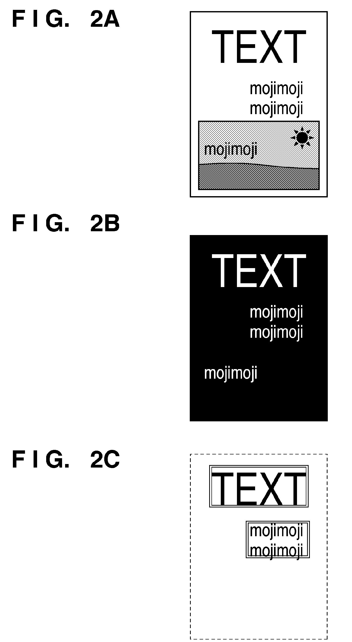
[0079]In the above-described first embodiment, the background image generator 103 generates a new background image by replacing pixel values of multi-valued image data corresponding to “1” pixels of a character image generated by the foreground image generator 104 with a value of a replacement color.

[0080]Generally, when an original having only characters is read as a multi-valued image with an image scanner, regarding a character edge as a boundary, an area outside the edge is not always white and an area within the edge is not always complete black. That is, in the neighborhood of an edge boundary, the luminance (or density) varies at a certain grade. Accordingly, even when multi-value pixel data in a pixel position determined as a character / line drawing is replaced with a replacement color, in a non-replacement pixel area adjacent to the replaced pixel, the density may be greatly changed due to the influence of an initial character color. In other words, there is a high possibili...

third embodiment

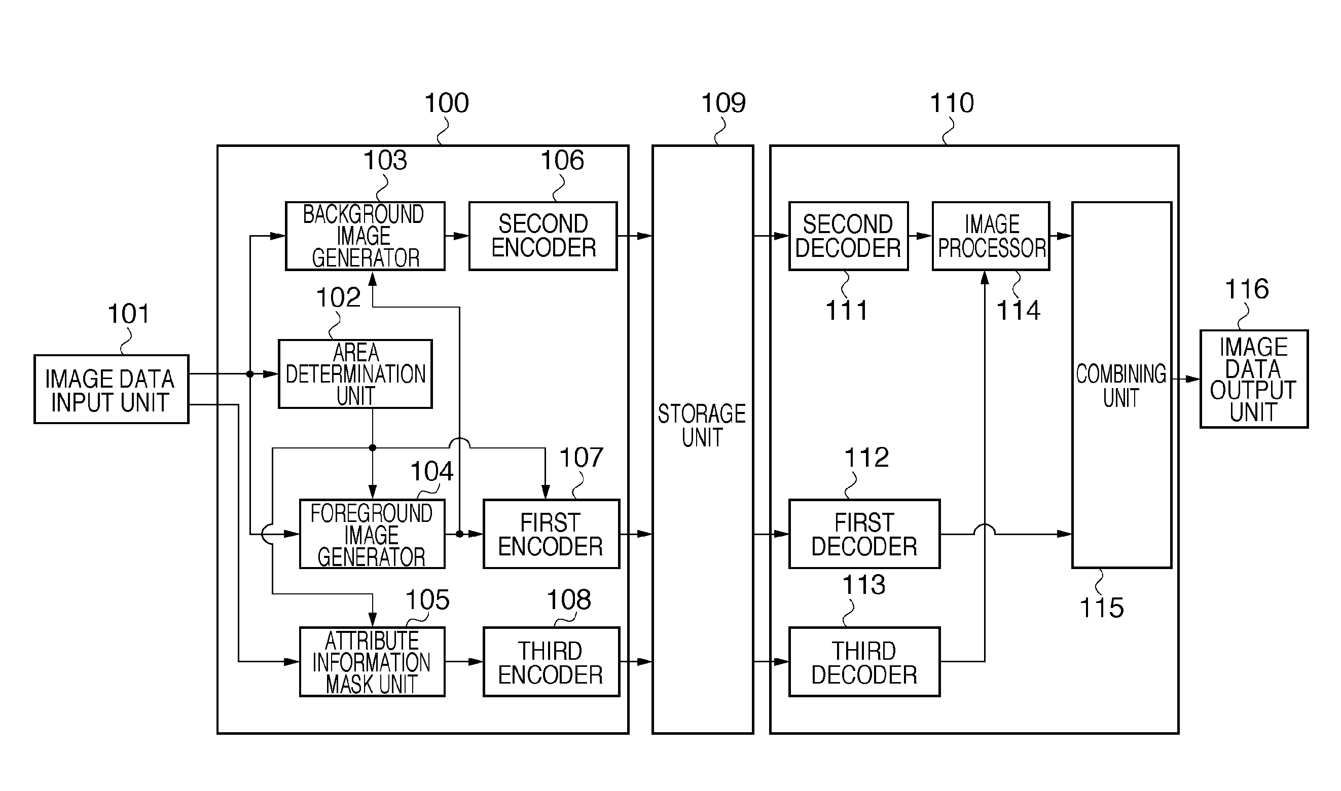
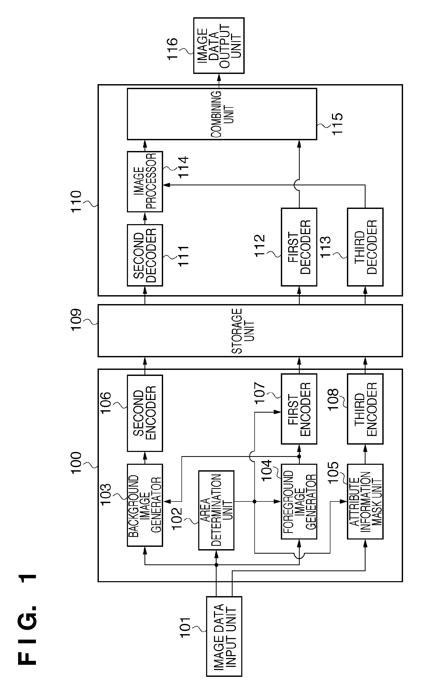
[0091]FIG. 6 is a block diagram of the multi-function apparatus according to a third embodiment. The difference from FIG. 1 is that the output from the first decoder 112 in the output image processor 110 is supplied to the third decoder 113. As the constituent elements are the same as those in the first embodiment except the output from the first decoder 112, the explanations of those elements will be omitted.

[0092]In the third embodiment, when character image data obtained by decoding by the first decoder 112 (binary image data) is “1”, the third decoder 113 outputs the result of decoding of the attribute data, even if it is “0” (a pixel constituting a character / line drawing), as “1”, to the image processor 114. On the other hand, when the character image data obtained by decoding by the first decoder 112 (binary image data) is “0” (a pixel of a non-character / line drawing), the third decoder 113 outputs the attribute data obtained by decoding to the image processor 114.

[0093]In thi...


PUM


Abstract

The invention provides an image encoding apparatus which can improve image quality of an output image while further reduce the amount of attribute. A determination unit determines an area including a character / line drawing as a foreground image area based on an input multi-valued image. A foreground image generator generates foreground image in binary representation so that a first encoder performs MMR encoding on the foreground image. A background image generator generates multi-valued background image data by replacing the value of a multi-valued pixel in a position of the character / line drawing in the foreground image area with a replacement value calculated from the pixel values in a position of the non-character / line drawing pixel. A second encoder performs JPEG encoding on the background image. A mask unit masks attribute for pixels within the foreground image area with a predetermined value to output the masked data to a third encoder.

Description

BACKGROUND OF THE INVENTION[0001]1. Field of the Invention[0002]The present invention relates to a technique for encoding image data.[0003]2. Description of the Related Art[0004]Conventionally, a technique for performing area separation processing on an image obtained by scanning, generating attribute map information indicating character areas and photographic areas to which each pixel belongs, and setting an image processing parameter in correspondence with the attribute map information, is known (see Japanese Patent Application Laid-Open No. 2006-140970).[0005]In this method, when a pixel is a character pixel, a “1” 1-bit signal is outputted, on the other hand, when the pixel is a photographic pixel, a “0” 1-bit signal is outputted. As a result, edge emphasis processing or the like is performed for character pixels to sharpen a character portion, while smoothing processing is performed for picture pixels. Thus an excellent output image, in which processings corresponding to respec...

Claims


Application Information

Patent Timeline
Patent Type & Authority Patents(United States)
IPC IPC(8): G06K9/46
CPCH04N19/60H04N19/17H04N19/12
Inventor MATSUMOTO, YUKI
Owner CANON KK
Why Eureka
Try Eureka