
Monitoring device

a monitoring device and a technology of a monitoring device, applied in the direction of hardware monitoring, program control, sustainable buildings, etc., can solve the problem of power consumption variation of the processor, and achieve the effect of rapid detection of faults

Inactive Publication Date: 2012-07-24
UNIVERSITY OF LEICESTER
View PDF4 Cites 3 Cited by
  • Summary
  • Abstract
  • Description
  • Claims
  • Application Information

AI Technical Summary

Benefits of technology

The present invention provides a monitoring device for a processor that can detect abnormal operation of the processor by analyzing its power consumption. The monitoring device is simple and non-invasive, as it does not require changes to the processor or the system it is monitoring. It can be used in real-time monitoring without affecting the performance of the processor. The monitoring device can also detect task overruns and alert the user or initiate a system-recovery operation. The invention is particularly useful for monitoring time-triggered systems where tasks are periodically executed. The power consumption of the processor can be monitored by measuring the potential difference across a known value of resistor in series with the processor's power input. The monitoring device can be configured to detect abnormal operation of the processor and alert the user or initiate a system-recovery operation. The invention provides a non-invasive technique for detecting task overruns in TTC embedded systems.

Problems solved by technology

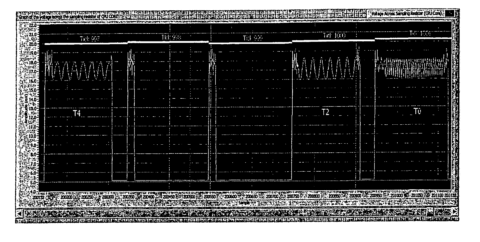
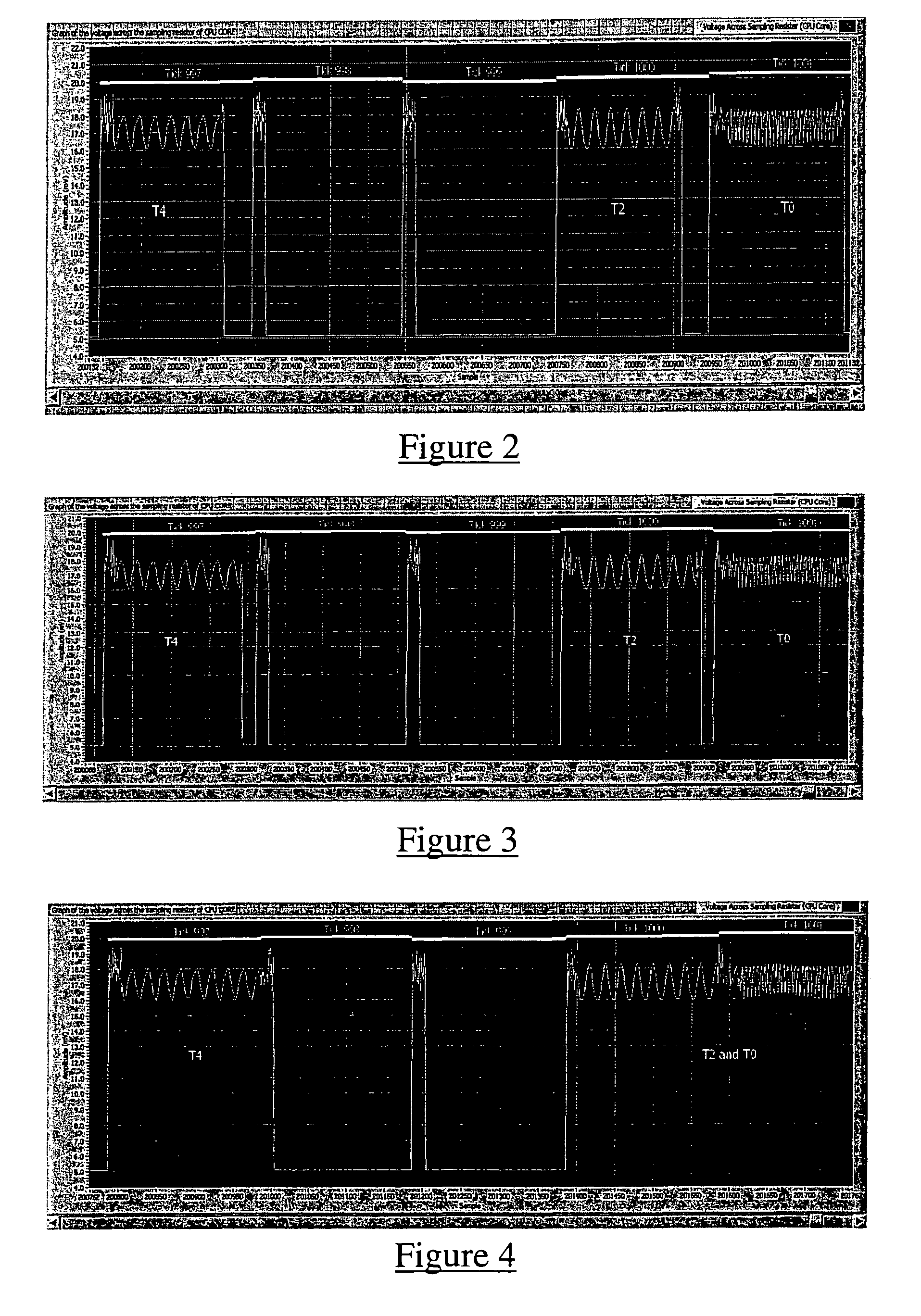
It is possible, but highly unlikely that different sets of instructions will consume the same quantities of energy and so it is likely that the power consumption of the processor will vary over time when a computer program is being executed.

Method used


Image

  • Monitoring device
  • Monitoring device
  • Monitoring device

Examples


Embodiment Construction

[0049]The present invention provides a device and method for passively monitoring a processor to detect abnormal behaviour.

[0050]In a particular embodiment of the present invention, the target processor comprises a TTC system. In TTC systems, tasks are executed periodically or on a one-shot basis within their scheduled processing times or deadlines. Such tasks are non pre-emptive, meaning that they run to completion once they start. This type of system can be implemented in different architectures, such as a super-loop architecture or a timer-based architecture.

[0051]In the timer-based architecture, such as employed in the embodiment of the present invention described below, an interrupt service routine (ISR) is triggered periodically, typically in every tick interval, to update the timing information for all tasks (i.e. to count down to when they are due to run). The ISR also executes tasks that are due to run in that particular tick interval.

[0052]As far as the power consumption o...


PUM


Abstract

The invention relates to a monitoring device for a processor comprising a means for monitoring the power consumption of the processor and a means for analysing the power consumption to detect abnormal operation of the processor.

Description

RELATED APPLICATIONS[0001]This application is a U.S. National Stage of International Application Serial No. PCT / GB2008 / 001602, filed May 9, 2008, and claims priority to United Kingdom Patent Application No. 0709113.5, filed May 11, 2007, the disclosures of which are hereby incorporated by reference in their entireties.FIELD OF THE INVENTION[0002]This invention relates to a monitoring device. Particularly, but not exclusively, the invention relates to a monitoring device suitable for detecting task overruns in time-triggered embedded systems.BACKGROUND TO THE INVENTION[0003]Embedded processors are ubiquitous: they form a core component of a vast range of everyday items (cars, aircraft, medical equipment, factory systems, mobile phones, DVD players, music players, microwave ovens, toys etc). In some cases several embedded processors may be employed, each for a specific function. For example, a typical modern car may contain around fifty embedded processors.[0004]In applications where ...

Claims


Application Information

Patent Timeline
Patent Type & Authority Patents(United States)
IPC IPC(8): G06F11/00
CPCG06F1/3203G06F9/4887G06F11/30Y02B60/144Y02D10/00
Inventor PONT, MICHAEL JOSEPHCHAN, KAM LEUNG
Owner UNIVERSITY OF LEICESTER
Learn More