
Toner, method of manufacturing toner, developer, two-component developer, developing device, and image forming apparatus

a manufacturing method and technology of toner, applied in the direction of instruments, electrographic process devices, developers, etc., can solve the problems of low quality of resultant images, less stable charge amount of toner, and complicated structure of developing devices, so as to achieve stable image formation, high resolution, and high definition

Active Publication Date: 2012-07-31
SHARP KK
View PDF21 Cites 0 Cited by
  • Summary
  • Abstract
  • Description
  • Claims
  • Application Information

AI Technical Summary

Benefits of technology

The invention provides a toner that has improved fixing and charging stability, resulting in high-quality images with high resolution and definition. The toner has a reduced tendency to adhere to the charge applying material, such as a carrier or regulating blade, which prevents flowability of the developer from deteriorating. The toner has a specific acid value and a specific amount of release agent exposed on its surface, which prevents the toner from flowing and sticking to the charge applying material. The release agent has a small dispersion diameter, which further prevents adherence to the charge applying material and maintains the flowability of the developer. The toner can be covered and / or encapsulated to further decrease contact with the charge applying material and improve its performance.

Problems solved by technology

In the two-component developer, the toner and the carrier are mixed with each other to give charges to the toner, and it is therefore necessary to provide a stirring mechanism for mixing the toner and the carrier evenly, which results in a disadvantage that the developing device will have more a complicated structure.
However, the toner is charged by friction with a plate-like blade made of metal or resin, which results in a disadvantage that a charge amount of the toner will be barely stable.
Such a toner as being composed of shape-controlled particles has however a problem that in the case of forming an image on a rough-surfaced recording medium, the resultant image will have low quality.
Further, the heat of the fixing device also increases the internal temperature of the developing tank.
As described above, when the amount of the release agent exposed on the surface of toner increases due to the shape control of toner particles, the toner and carrier in the developer will start to aggregate from the part of release agent exposed on the surface of toner, and such aggregation will deteriorate flowability of the developer, or will cause the release agent to be fused and fixed to the regulating blade.
However, in the toner contained in the electrostatic latent image developer disclosed by JP-A 9-319158, the amount of the wax exposed on the surface of the toner is too large to sufficiently curb the increase in the adherence of the toner to the carrier caused by the internal temperature rise of the developing tank, and it is therefore difficult to sufficiently prevent the flowability of the developer from deteriorating.
Besides, the recent downsizing and speeding-up trend of image forming apparatus causes a further rise in the internal temperature of the developing tank, which leads to a more obvious decline in the flowability of the developer.
In the electrostatic charge image developing toner disclosed by JP-A 2008-20578, the external additive present on the release agent part in the surfaces of the toner base particles is defined, but the percentage of the release agent exposed on the surfaces of the toner base particles is too high to sufficiently curb the increase in the adherence of the toner to the carrier caused by the internal temperature rise of the developing tank, and it is therefore difficult to sufficiently prevent the flowability of the developer from deteriorating.
Besides, the recent downsizing and speeding-up trend of image forming apparatus causes a further rise in the internal temperature of the developing tank, which leads to a more obvious decline in the flowability of the developer.

Method used


Image

  • Toner, method of manufacturing toner, developer, two-component developer, developing device, and image forming apparatus
  • Toner, method of manufacturing toner, developer, two-component developer, developing device, and image forming apparatus
  • Toner, method of manufacturing toner, developer, two-component developer, developing device, and image forming apparatus

Examples


example 1

Preliminarily Mixing Step

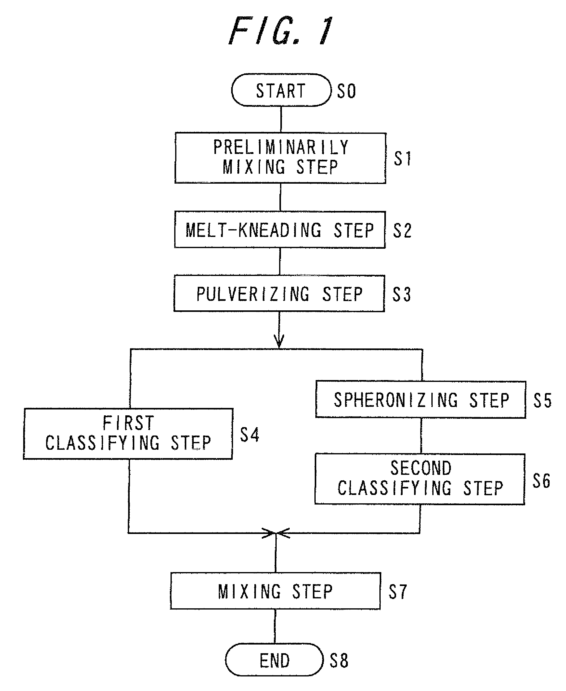
[0236]Using a Henschel mixer, the following materials were mixed for 10 minutes: 81.8 parts by weight of polyester resin A; 12 parts by weight of master batch (containing 40% by weight of C.I. pigment red 57:1); 5.0 parts by weight of paraffin wax which serves as a release agent: HNP10 (trade name) manufactured by Nippon Seiro Co., Ltd., having an acid value of zero mgKOH / g and a melting temperature of 75° C.; and 1.5 parts by weight of alkyl salicylate metal salt which serves as a charge control agent: BONTRON E-84 (trade-name) manufactured by Orient Chemical Industries, Ltd. An admixture was thus prepared.

[0237][Melt-Kneading Step]

[0238]The above admixture was then melt-kneaded by an open roll-type continuous kneader: MOS320-1800 (trade name) manufactured by Mitsui Mining Co., Ltd. A melt-kneaded product was thus prepared.

[0239][Pulverizing Step]

[0240]The melt-kneaded product was coarsely pulverized by means of a cutting mill: VM-16 (trade name) manufactur...

example 2

[0253]A toner of Example 2 and a two-component developer containing the toner were manufactured in the same manner as in Example 1, except that the amount of the release agent added in the preliminarily mixing step was changed from 5.0 parts by weight to 5.8 parts by weight.

example 3

[0254]A toner of Example 3 and a two-component developer containing the toner were manufactured in the same manner as in Example 1, except that the amount of the release agent added in the preliminarily mixing step was changed from 5.0 parts by weight to 4.2 parts by weight.


PUM


Abstract

A toner, a developer, a two-component developer, a developing device and an image forming apparatus are provided. In the image forming apparatus, images are formed with a developer that fills a developing tank of the developing device. The developer includes the toner containing at least a binder resin, a colorant, and a release agent, the release agent having an acid value of less than 4 mgKOH / g and in which an amount of the release agent exposed on a surface of toner is 0.5% by weight or more and 2.5% by weight or less of a total amount of the toner.

Description

CROSS-REFERENCE TO RELATED APPLICATION[0001]This application claims priority to Japanese Patent Application Nos. 2008-040679 and 2008-151115, which were filed on Feb. 21, 2008 and Jun. 9, 2008, the contents of which are incorporated herein by reference in its entirety.BACKGROUND OF THE-INVENTION[0002]1. Field of the Invention[0003]The present invention relates to a toner, a method of manufacturing the toner, a developer, a two-component developer, a developing device, and an image forming apparatus having the developing device.[0004]2. Description of the Related Art[0005]A toner is used to visualize a latent image in various image forming processes, and one known example thereof is an electrophotographic image forming process.[0006]An electrophotographic image forming apparatus forming images in the electrophotography process is capable of easily forming images with high quality and therefore is widely used for copiers, printers, facsimile machines, and the like equipment.[0007]The ...

Claims


Application Information

Patent Timeline
Patent Type & Authority Patents(United States)
IPC IPC(8): G03G9/00
CPCG03G9/081G03G9/0825G03G9/08782G03G9/08795G03G9/09716G03G9/09725G03G15/1605G03G2215/0607
Inventor TSUBAKI, YORITAKAONDA, HIROSHIIMURA, YASUO
Owner SHARP KK
Learn More