Fixed type constant velocity universal joint

a constant velocity, universal joint technology, applied in the direction of yielding couplings, lubricant compositions, base materials, etc., can solve the problems of stick slippage and abnormal noise of drivers, and achieve the effects of maintaining the viscous state of grease, cost advantage, and shear stability

Active Publication Date: 2016-01-26
NTN CORP
View PDF19 Cites 0 Cited by
  • Summary
  • Abstract
  • Description
  • Claims
  • Application Information

AI Technical Summary

Benefits of technology

[0027]In the fixed type constant velocity universal joint of the present invention, grease enclosed in the joint contains 80% by mass or more of paraffinic mineral oil or a mixture of paraffinic mineral oil and synthetic hydrocarbon oil with respect to the total mass of a lubricant component contained as base oil, the paraffinic mineral oil accounts for 70% by mass or more of the total mass of the lubricant component, and the grease contains 3 to 8% by mass of a thickener with respect to the total mass of the components of the grease, so that the flowability of the grease at a low temperature can be ensured to prevent stick slip and abnormal noises at low temperatures from occurring.
[0028]In other words, typically, the base oil is unlikely to flow at a low temperature, and the thickener in which the base oil is held in the mesh structure by a surface tension functions to inhibit the flowability of the grease at a low temperature. Of the base oil, the paraffinic mineral oil or the synthetic hydrocarbon oil is unlikely to flow at a low temperature like the naphthenic mineral oil, but when subjected to shear from the movement of the inside of the fixed type constant velocity universal joint, the viscosity of the paraffinic mineral oil becomes abruptly smaller than that of the naphthenic mineral oil. When the amount of the thickener is too large, the flowability of the base oil subjected to shear is inhibited, so that it should be smaller. On the contrary, the amount necessary for maintaining the viscous state of the grease needs to be ensured. In addition, the shear stability in a typically used temperature range needs to be ensured. Therefore, the grease needs to contain 3 to 8% by mass of the thickener.
[0029]In addition, the grease contains 80% by mass or more of a mixture of paraffinic mineral oil and synthetic hydrocarbon oil with respect to the total mass of a lubricant component contained as base oil, and the paraffinic mineral oil accounts for 70% by mass or more of the total mass of the lubricant component, and in this way, the amount of the paraffinic mineral oil is larger and the amount of the synthetic hydrocarbon oil is smaller, so that cost advantage can be obtained.
[0030]Together with the above structure, the thickener is a urea compound and the grease contains 3 to 8% by mass of the thickener, so that the engulfment of the base oil in an extremely cold environment can be reduced, and with this, the flowability of the grease can be ensured, thereby preventing stick slip from occurring.
[0031]In addition to the above structure, the grease contains 0 to 20% by mass of ester oil with respect to the total mass of the lubricant component contained as the base oil, so that the proper viscosity can be obtained, and the swelling properties to a boot material which is insufficient due to the large mixing proportion of the paraffinic mineral oil can be moderately ensured. In addition, the amount of ester oil to be mixed is small, which is desirable in cost.
[0032]Further, the grease contains 20% by mass or less of naphthenic mineral oil with respect to the total mass of the lubricant component contained as the base oil, so that stick slip at low temperatures and abnormal noises at low temperatures caused thereby can be prevented from occurring.

Problems solved by technology

In such a case, immediately after torque is inputted to the fixed type constant velocity universal joint at a high operating angle, stick slip can occur due to temporary lack of lubricity between the track grooves in the joint and the balls guided in the track grooves.
When such stick slip occurs, the driver can hear abnormal noises.
Since the abnormal noises at low temperatures disappear immediately when the joint is rotated to generate heat for increasing the temperature therein, the noises become a problem only when the vehicle left in a low temperature environment for a long time is driven and do not become a problem other than immediately after it is driven.

Method used


Image

  • Fixed type constant velocity universal joint
  • Fixed type constant velocity universal joint
  • Fixed type constant velocity universal joint

Examples


examples

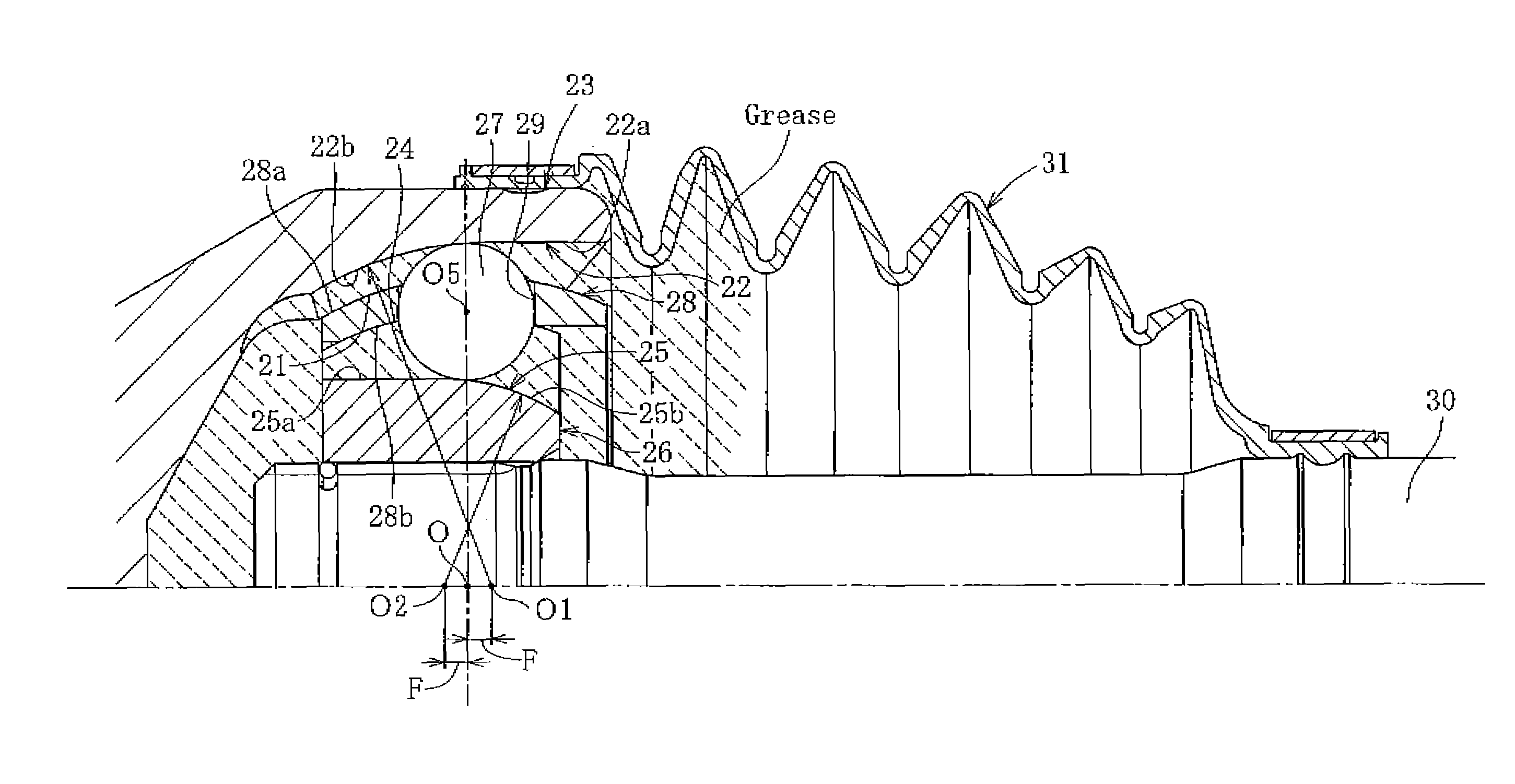
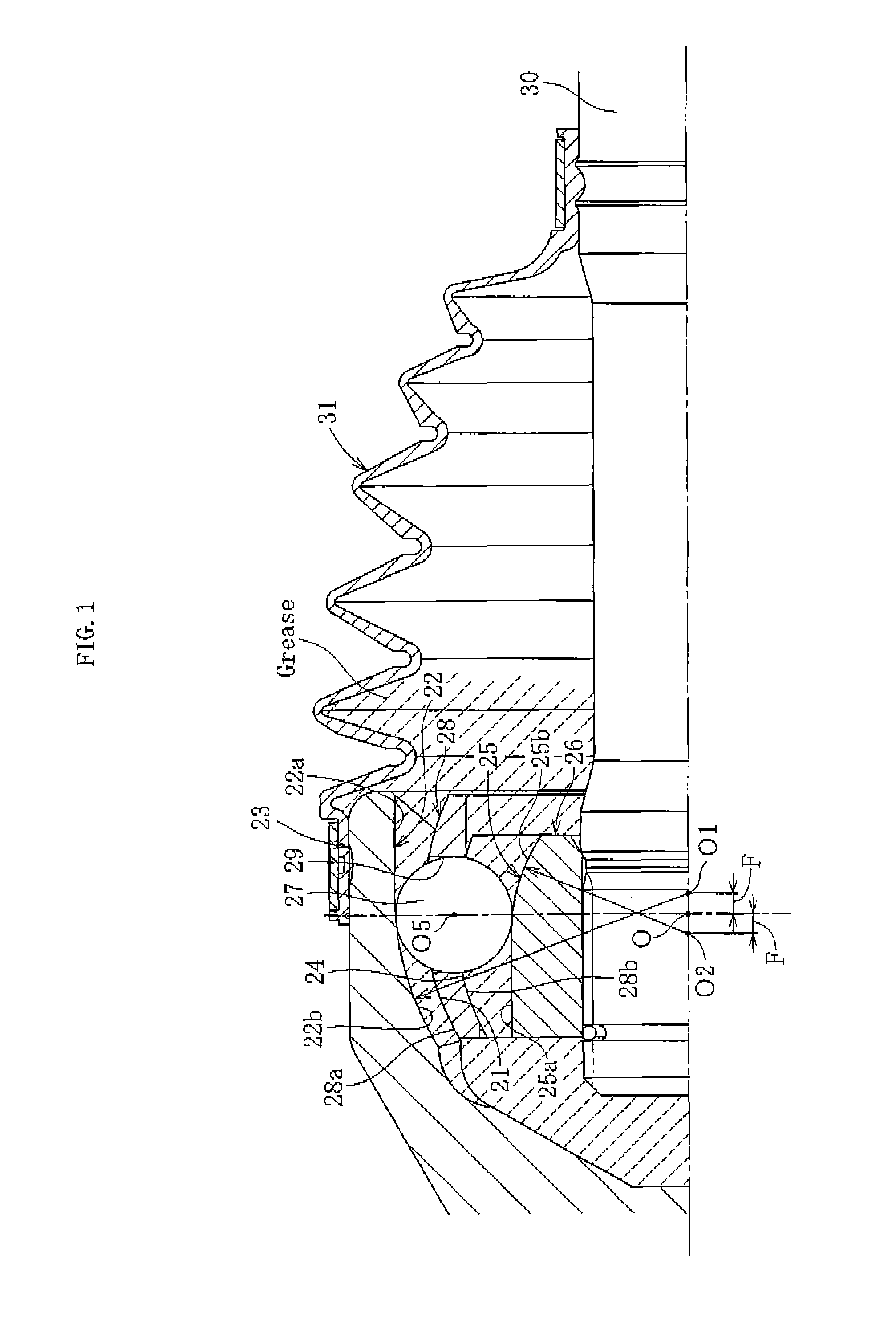
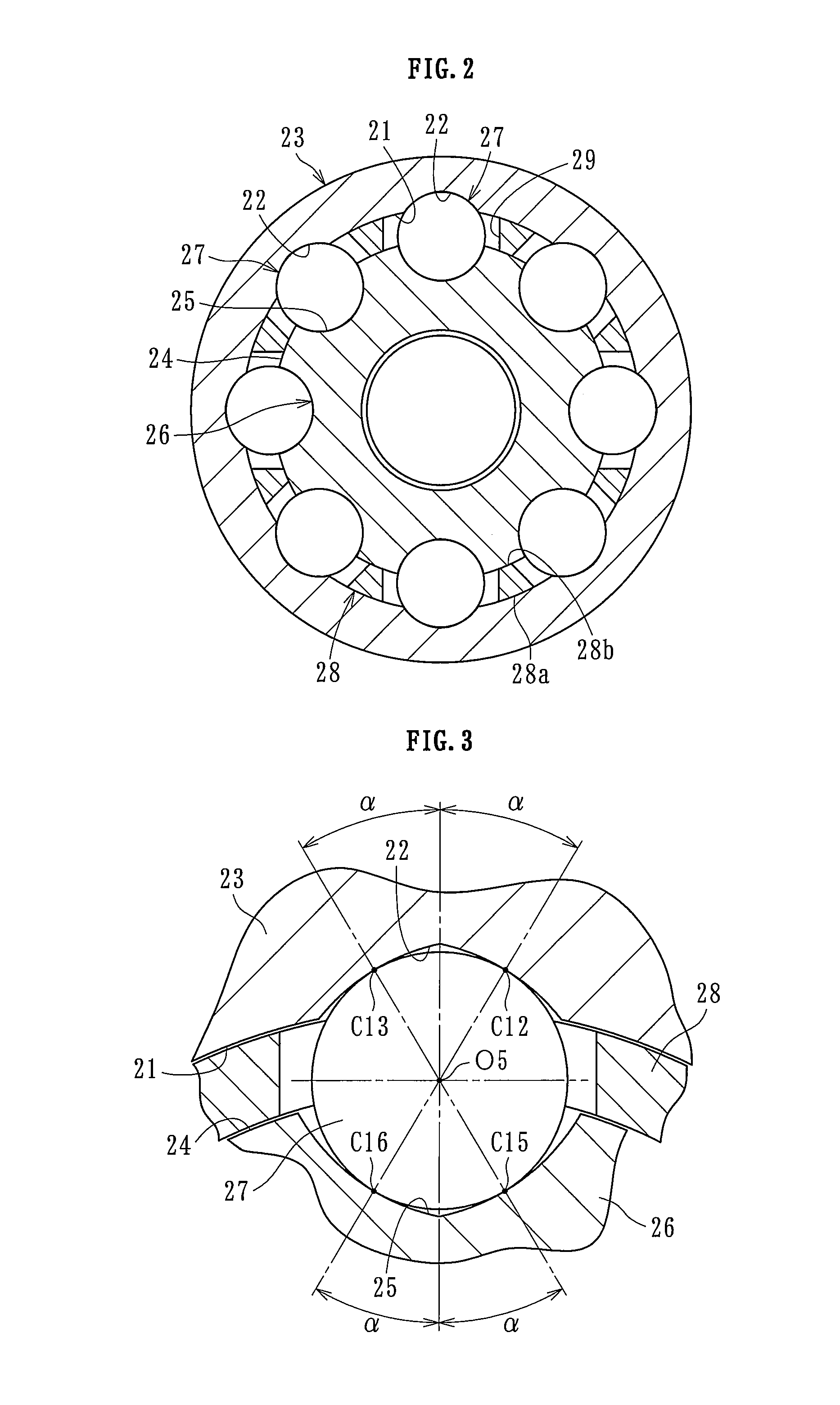
[0055]Hereinafter, examples of the present invention and comparative examples will be described. The compositions of the greases enclosed in the fixed type constant velocity universal joints of the examples and the comparative examples are shown in Table 2. In Table 2, for convenience, the examples and the comparative examples are shown in the section above the compositions of the greases, which means that the examples and the comparative examples are the fixed type constant velocity universal joints which enclose the respective greases. The examples and the comparative examples in Table 2 are all the fixed type constant velocity universal joint of the undercut-free type having eight balls, whose structure has been described in the embodiment.

[0056]In the following examples and comparative examples, considering the durability, as the additives, several % by mass of molybdenum dithiocarbamate (MODTC), molybdenum dithiophosphate (MODTP), zinc dithiocarbamate (ZnDTC), zinc dithiophosph...


PUM

PropertyMeasurementUnit
temperaturesaaaaaaaaaa
temperatureaaaaaaaaaa
friction coefficientaaaaaaaaaa

Abstract

A fixed type constant velocity universal joint includes an outer joint member, an inner joint member, a plurality of balls for transmitting torque provided between track grooves of the outer joint member and track grooves of the inner joint member, and a cage for retaining the balls. Grease is enclosed in the fixed type constant velocity universal joint which includes a thickener and a lubricant component which is constituted by base oil. The grease contains 90% by mass or more of paraffinic mineral oil with respect to the total mass of the lubricant component of the grease, and 3 to 8% by mass of the thickener with respect to the total mass of the components of the grease.

Description

TECHNICAL FIELD[0001]The present invention relates to a fixed type constant velocity universal joint which is used in power transmission systems of vehicles such as automobiles and allows only the angular displacement between two shafts on the driving side and the driven side, and more particularly, to a fixed type constant velocity universal joint which can prevent stick slip from occurring due to lack of lubricity even during use in an extremely cold region.BACKGROUND ART[0002]As shown in FIG. 6, a Rzeppa type constant velocity universal joint which is a fixed type constant velocity universal joint includes an outer joint member 3, an inner joint member 6, balls 7, and a cage 8. The outer joint member 3 has a spherical inner surface 1 in which a plurality of track grooves 2 are formed in the circumferential direction at regular intervals and along the axial direction. The inner joint member 6 has a spherical outer surface 4 in which track grooves 5 opposite the track grooves 2 of ...

Claims


Application Information

Patent Timeline
Patent Type & Authority Patents(United States)
IPC IPC(8): C10M101/02F16D3/2237F16D3/224C10M111/04F16D3/2245F16D3/223
CPCF16D3/2237C10M101/02C10M111/04F16D3/2245C10M2203/1025C10M2203/1065C10M2205/028C10M2205/173C10M2207/2805C10M2207/285C10M2215/1026C10M2219/068C10M2223/045C10N2220/022C10N2230/08C10N2230/36C10N2240/046C10N2250/10F16D2003/22309C10N2210/02C10N2210/06C10M169/02C10N2020/02C10N2030/08C10N2030/36C10N2040/046C10N2050/10C10N2010/12C10N2010/04
Inventor KOBAYASHI, TOMOSHIGEISHIJIMA, MINORUYAMAZAKI, KISAOISHIKAWA, AIKO
Owner NTN CORP
Why Eureka
Try Eureka