Patch jittering for visual artifact correction

a visual artifact and jittering technology, applied in the field of jittering for visual artifact correction, can solve the problems of large amounts of time and resources, large computational complexity of techniques, and difficulty in making changes using existing editing tools, and achieve the effect of repairing visual artifacts and maximizing the probability of active label assignmen

Active Publication Date: 2012-07-31
ADOBE SYST INC
View PDF11 Cites 22 Cited by
  • Summary
  • Abstract
  • Description
  • Claims
  • Application Information

AI Technical Summary

Benefits of technology

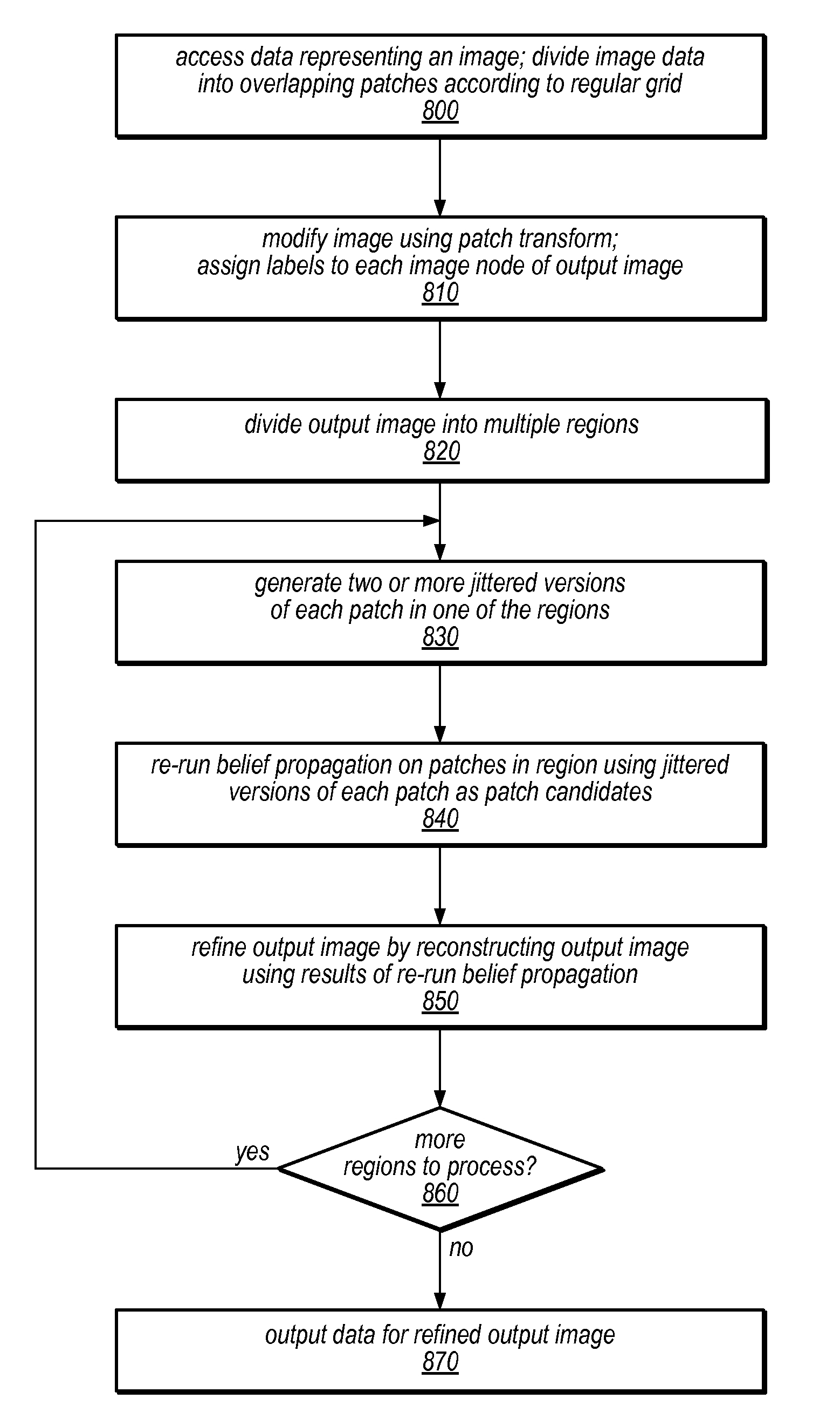
[0007]In some embodiments, some or all of the patches are overlapping patches, and these patches may be jittered to correct visual artifacts in the reconstructed output image. One or more jittered versions of a patch initially assigned to a node in the output image may be generated and included in a set of candidate patches to be assigned to the corresponding node in a refined output image. A jittered version of a patch may be a version of the patch that has been shifted by a small number of pixels in a horizontal and / or vertical direction. In some embodiments, the amount of jittering exhibited by each jittered version of a given patch and / or the number of jittered versions of the given patch to be generated and / or considered for placement in the refined image may be configurable (e.g., programmatically, or by a user). In other embodiments, the amount of jitter exhibited by the jittered versions of a given patch may be dependent on the amount of overlap between the given patch and an adjacent patch in the output image. In some embodiments, one or more jittered versions of each patch of an image may be pre-computed (e.g., prior to or in response to an image editing operation), and may subsequently be used in correcting of visual artifacts.
[0008]In some embodiments, belief propagation may be used to determine a correction solution in which one of the jittered versions of one or more patches initially assigned to various nodes in the output image replace corresponding nodes in a refined output image such that the joint probability of active label assignments is maximized and visual artifacts are repaired.

Problems solved by technology

These types of changes can be difficult to make using existing editing tools.
However, these techniques are computationally complex and consume large amounts of both time and resources.

Method used


Image

  • Patch jittering for visual artifact correction
  • Patch jittering for visual artifact correction
  • Patch jittering for visual artifact correction

Examples


Embodiment Construction

[0023]In the following detailed description, numerous specific details are set forth to provide a thorough understanding of claimed subject matter. However, it will be understood by those skilled in the art that claimed subject matter may be practiced without these specific details. In other instances, methods, apparatuses or systems that would be known by one of ordinary skill have not been described in detail so as not to obscure claimed subject matter.

[0024]Some portions of the detailed description which follow are presented in terms of algorithms or symbolic representations of operations on binary digital signals stored within a memory of a specific apparatus or special purpose computing device or platform. In the context of this particular specification, the term specific apparatus or the like includes a general purpose computer once it is programmed to perform particular functions pursuant to instructions from program software. Algorithmic descriptions or symbolic representati...


PUM


Abstract

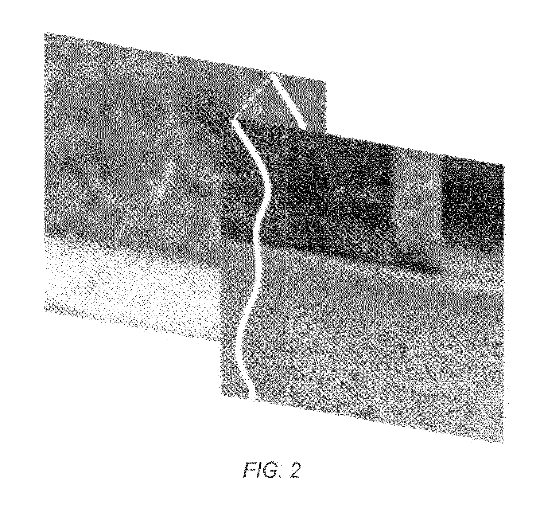
Systems and methods for performing image editing operations may use patch transforms and inverse patch transforms to reconstruct output images from input images and to refine them using patch jittering such that visual artifacts are repaired. The methods may include generating one or more jittered versions of patch(es) initially assigned to nodes of the output image and using them as candidate patches for a refined image. Jittered versions of patches may be shifted by a small number of pixels in one or more directions. The number of jittered versions and amount of jittering exhibited by each may be configurable (e.g., programmatically or by a user) and / or may be dependent on the amount of overlap between the patches. Belief propagation may be used to replace patches in the output image with jittered versions in the refined image. The methods may be implemented as program instructions executable on a CPU and / or GPU.

Description

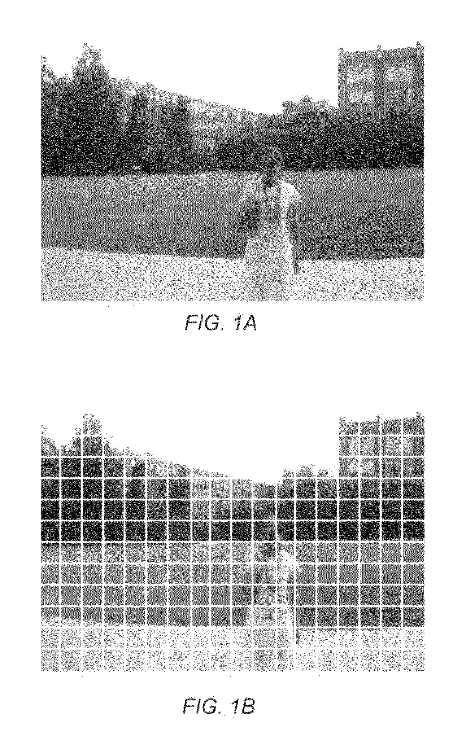
PRIORITY INFORMATION[0001]This application claims benefit of priority of U.S. Provisional Application Ser. No. 61 / 093,121 entitled “Patch Jittering for Visual Artifact Correction” filed Aug. 29, 2008, the content of which is incorporated by reference herein in its entirety.BACKGROUNDDescription of the Related Art[0002]Graphic applications include an ever-increasing number of image editing features, such as various filtering options, image feature relocation operations, and resizing operations (e.g., for cropping, expanding, or reducing an image). A user may want to make various changes to an image, such as changes in the position of objects, or changes to textures. These types of changes can be difficult to make using existing editing tools.[0003]Some previous techniques on image matting and image composition work at a pixel-level accuracy, and have been shown to perform well in extracting foreground layers in images and placing them on a new background. However, these techniques ar...

Claims


Application Information

Patent Timeline
Patent Type & Authority Patents(United States)
IPC IPC(8): G06K9/36
CPCG06T11/60
Inventor CHO, TAEG SANGAVIDAN, SHMUELFREEMAN, WILLIAM T.
Owner ADOBE SYST INC
Why Eureka
Try Eureka