Interlocked CMC airfoil

a technology of airfoil and composite materials, applied in the direction of machines/engines, stators, liquid fuel engines, etc., can solve the problems of cyclic stress at the trailing edge, interlaminar tensile stress concentrated at the inner radius of the trailing edge,

Inactive Publication Date: 2012-08-07
SIEMENS ENERGY INC
View PDF6 Cites 31 Cited by
  • Summary
  • Abstract
  • Description
  • Claims
  • Application Information

AI Technical Summary

Problems solved by technology

A curved CMC wall has a minimum radius of curvature if any of the ceramic fibers wrap around the curve, due to limited flexibility of the fibers.
For laminated constructions, this internal pressure results in an interlaminar tensile stress concentrated at the inner radius of the trailing edge, which tends to be a design-limiting feature.
Gas pressures inside and outside of the airfoil vary with engine cycles, causing cyclic stress at the trailing edge.

Method used


Image

  • Interlocked CMC airfoil
  • Interlocked CMC airfoil
  • Interlocked CMC airfoil

Examples


Embodiment Construction

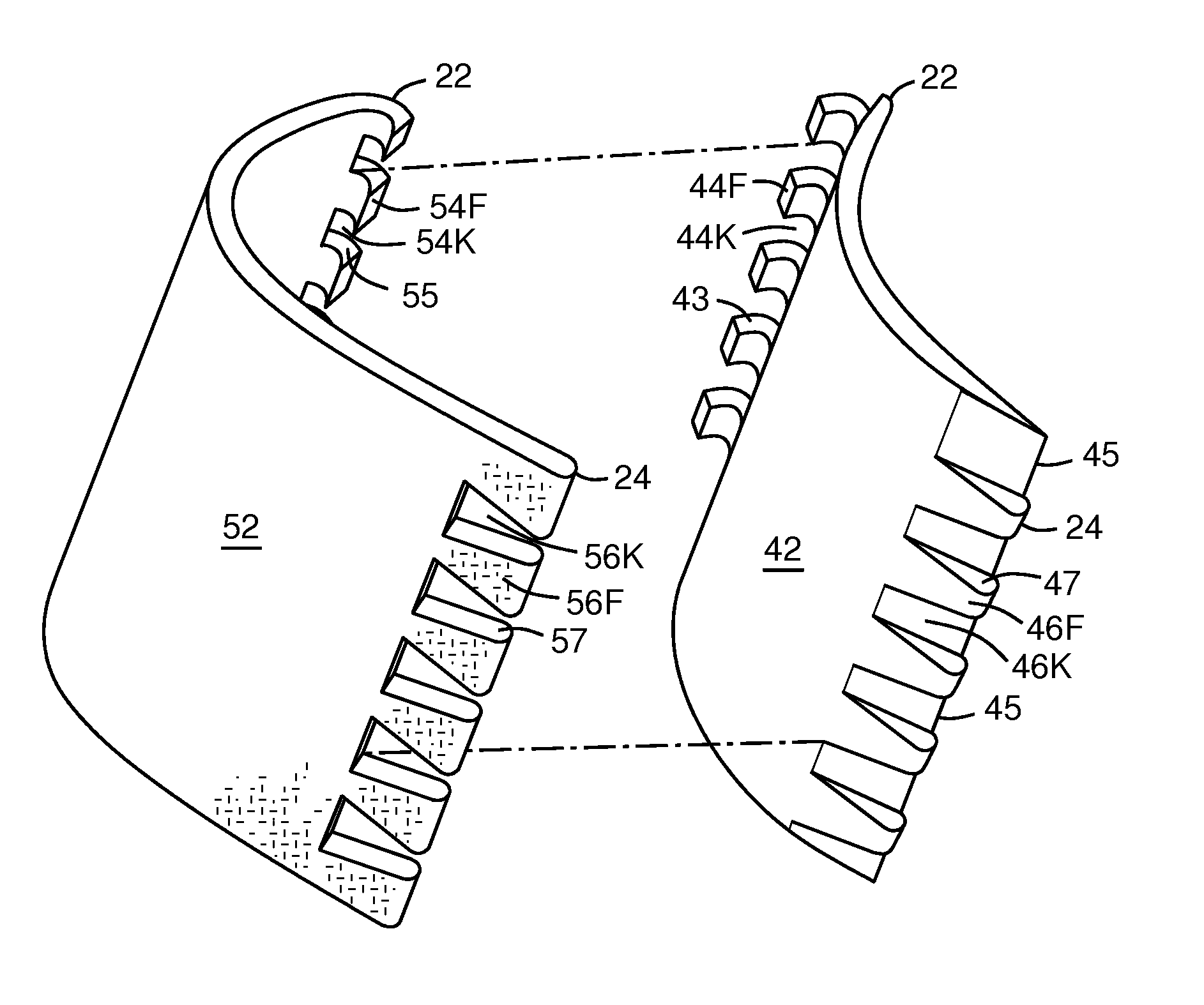
[0022]The inventors have recognized that a thin CMC trailing edge can be achieved by forming an airfoil in two parts, a pressure side wall part and a suction side wall part, tapering the trailing edges of the two parts and bonding them together. However, the resulting trailing edge joint might not be sufficiently resistant to separation and delamination from the stresses previously described, so they conceived the following interlocking airfoil assembly.

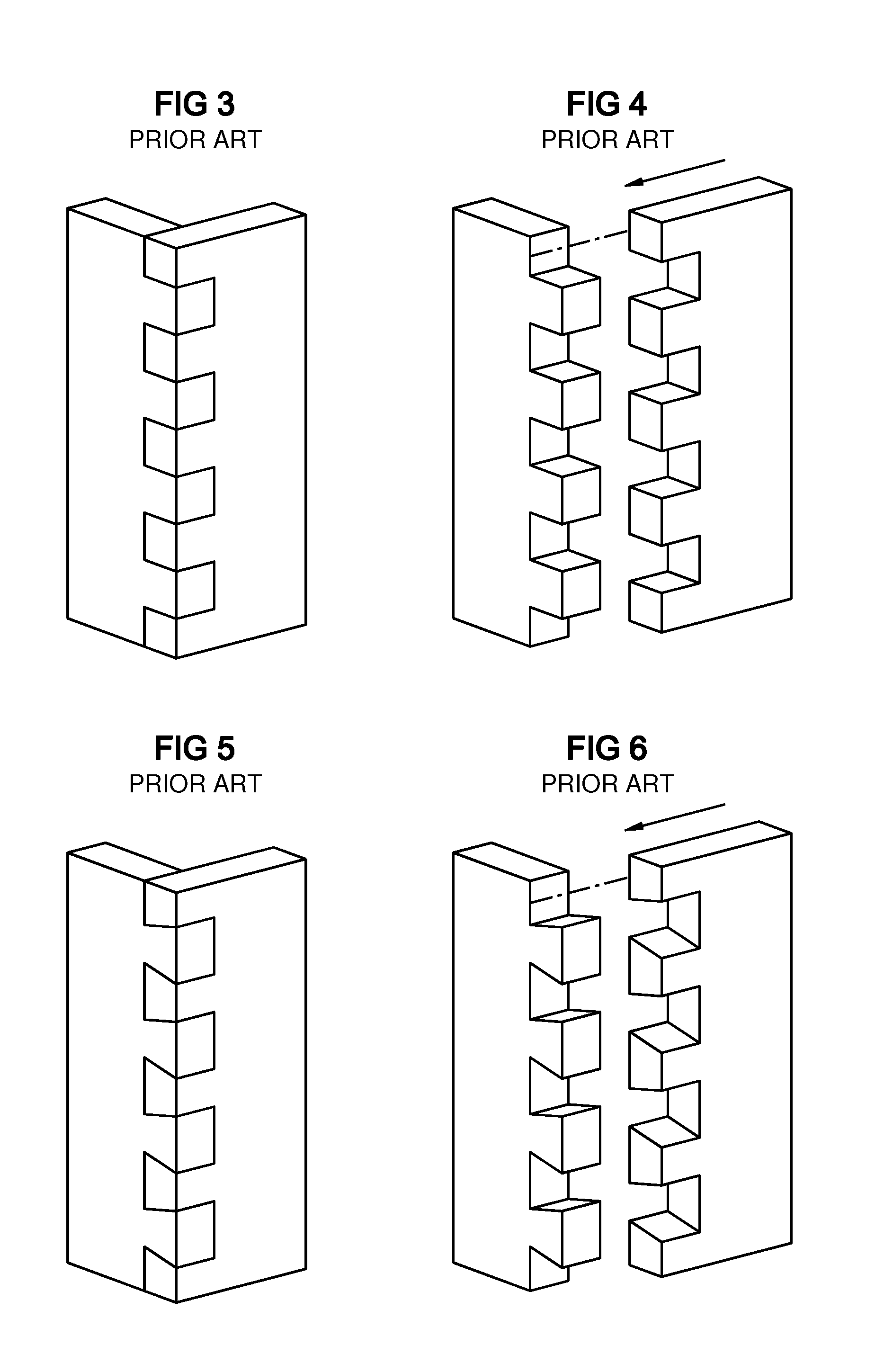
[0023]FIGS. 3 and 4 show a finger joint known in cabinet making. This joint interlocks and prevents relative vertical movement of the two joined parts. It also provides an increased bonding surface with very strong separation resistance. FIGS. 5 and 6 show a dovetail joint known in cabinet-making. This joint can only be assembled along a single direction shown by the arrow, so it prevents separation in all directions except the reverse of the assembly direction. However, application of these types of woodworking joints to an airfoil ...


PUM

PropertyMeasurementUnit
thicknessaaaaaaaaaa
thicknessesaaaaaaaaaa
radiusaaaaaaaaaa

Abstract

A ceramic matrix composite (CMC) airfoil assembled from a pressure side wall (42) and a suction side wall (52) joined by interlocking joints (18, 19) at the leading and trailing edges (22, 24) of the airfoil to produce a tapered thin trailing edge. The trailing edge (24) is thinner than a combined thicknesses of the airfoil walls (42, 52). One or both of the interlocking joints (18, 19) may be formed to allow only a single direction of assembly, as exemplified by a dovetail joint. Each joint (18, 19) includes keys (44F, 54F, 56F, 46F) on one side and respective keyways (44K, 54K, 56K, 46K) on the other side. Each keyway may have a ramp (45) that eliminates indents in the airfoil outer surface that would otherwise result from the joint.

Description

FIELD OF THE INVENTION[0001]This invention relates to ceramic matrix composite (CMC) airfoil structures, and particularly to gas turbine vanes.BACKGROUND OF THE INVENTION[0002]Ceramic matrix composites (CMC) are used for components in high temperature environments, such in gas turbine engines. Oxide based CMC is typically formed by combining ceramic fibers with a ceramic matrix, and heating the combined material to a sintering temperature. The fibers add tensile strength in the directions of the fibers. The resulting material has a higher operating temperature range than metal, and can be optimized for strength by fiber orientations and layering.[0003]A curved CMC wall has a minimum radius of curvature if any of the ceramic fibers wrap around the curve, due to limited flexibility of the fibers. This presents problems in CMC airfoil fabrication, because an airfoil preferably has a thin trailing edge. FIG. 1 shows an airfoil with a leading edge 22, a trailing edge 24, a pressure side ...

Claims


Application Information

Patent Timeline
Patent Type & Authority Patents(United States)
IPC IPC(8): F01D5/14
CPCF01D5/147F01D5/282F04D29/023F04D29/542F01D5/284Y10T29/49339F05D2300/608F05D2230/23F05D2300/6033
Inventor MORRISON, JAY A.SCHIAVO, ANTHONY L.
Owner SIEMENS ENERGY INC
Why Eureka
Try Eureka