Scleral depressor

a scleral depressor and scleral tube technology, applied in the field of scleral tube depressors, can solve the problems of difficult use of conventional and unconventional scleral tube depressors in conjunction with other instruments, and the scleral tube is not ideally suited, and achieves the effects of good control of the globe, convenient use for the examiner, and adequate visualization of the periphery

Active Publication Date: 2012-08-07
JOSEPHBERG ROBERT G +1
View PDF14 Cites 5 Cited by
  • Summary
  • Abstract
  • Description
  • Claims
  • Application Information

AI Technical Summary

Benefits of technology

[0009]There is a need to make a scleral depressor that can not only maintain good control of the globe of the eye and provide adequate visualization of the periphery, but is also easy to use for the examiner and comfortable for the patient.
[0010]A scleral depressor designed to better control the globe of the eye is disclosed. In a preferred embodiment, the scleral depressor has a handle and a blade attached to the handle where the blade is a portion of an oblate spheroid. In one embodiment, the blade has an illuminating device. The handle is attached to the blade at an angle or straight in relation to the plane of the handle. In another embodiment, the blade is attached to a thimble. In another embodiment of the invention, the blade has an access hole for simultaneous use of other instruments during examination or surgery. The resulting apparatus has greatly improved control of the eye, effective visualization of the periphery, ease of use for the examiner, and increased comfort for the patient.

Problems solved by technology

These type of scleral depressors are not ideally suited for examination for the following general reasons: (a) the tips of these depressors are bulky and with a pediatric lid speculum in place it is often difficult to find adequate room to insert an instrument into the conjunctival sac; (b) undue pressure on the globe and compromise of the ocular circulation is therefore possible; and (c) these scleral depressors have smooth surfaces, slide on the globe, and will not rotate it to different examination positions.
Additionally, both the conventional and unconventional scleral depressors are often difficult to use in conjunction with other instruments because they are not designed for operation from a position which will leave the field substantially clear for the simultaneous use of these instruments in the examination of the eye.

Method used


Image

  • Scleral depressor
  • Scleral depressor
  • Scleral depressor

Examples


Embodiment Construction

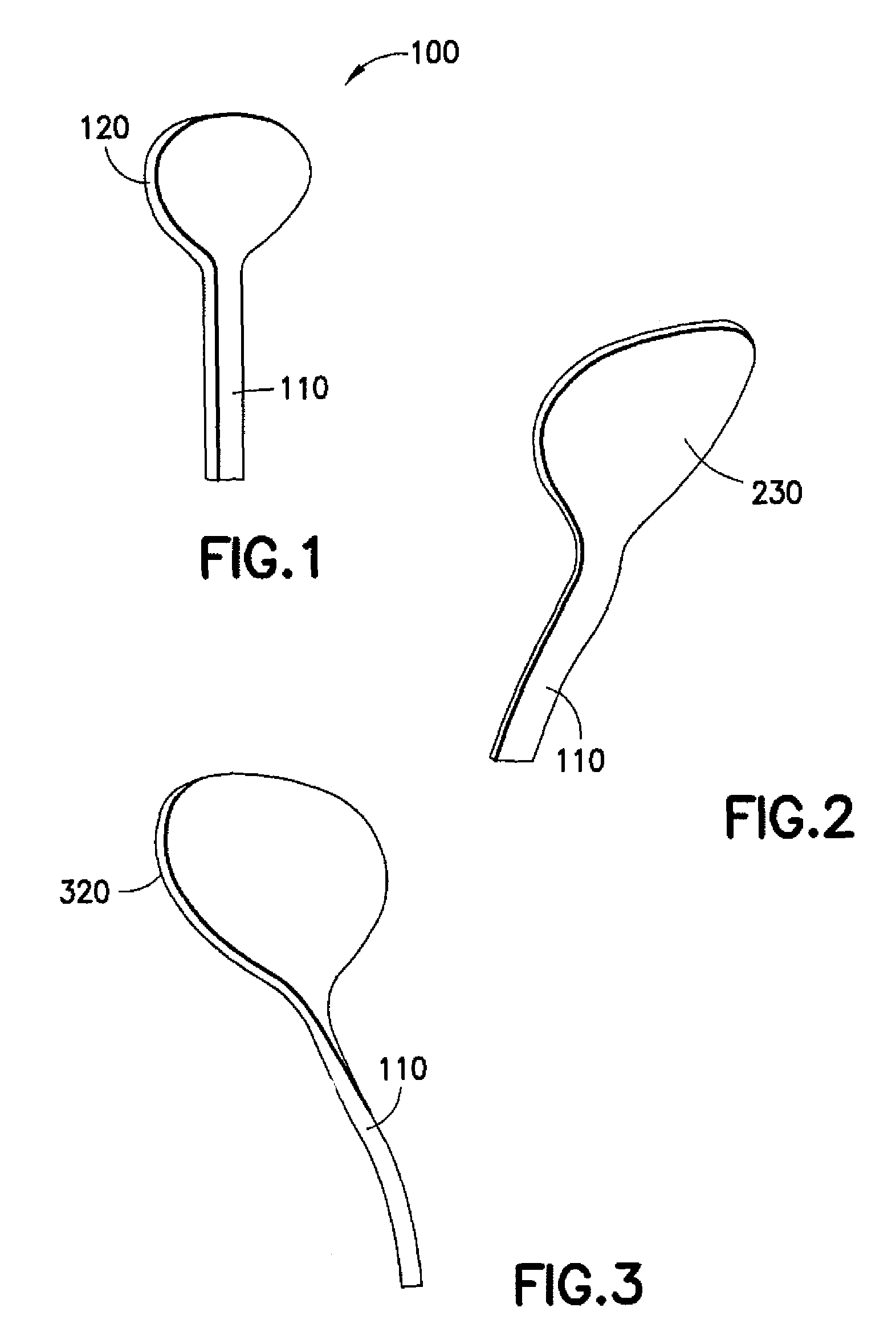
[0022]During fundus examination, the slender oblong curved blade of the disclosed scleral depressor can be easily positioned around the globe, whether over the eyelid, along the crease when examining the superior and inferior peripheral retina, or directly on the globe in the medial or lateral conjunctival sac when evaluating the medial or temporal peripheral fundus. The oblong curved blade is wider than the T-bar tip or bulbous end of conventional scleral depressors. Thus, it indents a larger surface area in the peripheral retina allowing visualization of a wider field with less manipulation of the globe. In a preferred embodiment, the oblong curved blade is substantially between ⅛ of an inch and 1 inch wide and between ⅛ of an inch and 1 inch long. In a preferred embodiment, the oblong curved blade is ¼ inch wide and ¾ inch long.

[0023]FIG. 1 illustrates a front elevational view of the scleral depressor 100, comprising a blade 120 and a handle portion 110. In this embodiment of the...


PUM


Abstract

A scleral depressor designed to better control the globe of the eye is disclosed. In a preferred embodiment, the scleral depressor has a handle and a blade attached to the handle where the blade is a portion of an oblate spheroid. In one embodiment, the blade has an illuminating device. The handle is attached to the blade at an angle or straight in relation to the plane of the handle. In another embodiment, the blade is attached to a thimble. In another embodiment of the invention, the blade has an access hole for simultaneous use of other instruments during examination or surgery. The resulting apparatus has greatly improved control of the eye, effective visualization of the periphery, ease of use for the examiner, and increased comfort for the patient.

Description

CROSS-REFERENCE TO RELATED APPLICATION[0001]This application claims priority to U.S. Provisional Application No. 60 / 847,924, which was filed on Sep. 29, 2006, and U.S. Provisional Application No. 60 / 868,877 which was filed on Dec. 6, 2006, and both are incorporated herein by reference in their entirety.FIELD OF THE INVENTION[0002]The present invention relates to an ophthalmic surgical and examination tool used for depressing the sclera during an eye examination. More particularly, the present invention relates to a scleral depressor that provides improved manipulation and control over eye position.BACKGROUND OF THE INVENTION[0003]A scleral depressor is used to facilitate examination of a fundus of an eye, particularly its periphery. During an ocular fundus examination, and particularly during the study of areas of the retina such as the periphery, it is necessary to control the position of the eye. Several sclera depressors have been designed for this purpose. For example, the Storz...

Claims


Application Information

Patent Timeline
Patent Type & Authority Patents(United States)
IPC IPC(8): A61B3/00
CPCA61B17/0231A61B2017/00557A61B2019/4889A61B2090/0817
Inventor JOSEPHBERG, ROBERT G.BESSER, EDUARDO
Owner JOSEPHBERG ROBERT G
Why Eureka
Try Eureka