Safety device to cover the needle tip of intravenous catheter apparatus

a safety device and catheter technology, applied in the direction of intravenous devices, infusion needles, infusion syringes, etc., can solve the problems of blood on or near the needle tip escaping from the needle guard, accidental pricking of used needles, and high risk of needle pricking

Active Publication Date: 2012-08-07
BAID RISHI
View PDF19 Cites 42 Cited by
  • Summary
  • Abstract
  • Description
  • Claims
  • Application Information

AI Technical Summary

Benefits of technology

[0006]A primary object of this invention is to propose a safety device for the needle of an intravenous catheter apparatus that facilitates and ensures safe disposal of the needle of the intravenous catheter apparatus after the needle is withdrawn from the vein of a patient following cannulation.
[0009]A further object of this invention is to propose a safety device for the needle of an intravenous catheter apparatus, which is big enough to cover the needle tip from all sides thereby preventing infected blood from oozing out of the safety device.
[0010]Yet another object of this invention is to propose a safety device for the needle of an intravenous catheter apparatus which may be fitted between a wing body and needle hub in such a way that it does not create any impediment to the function and operation of the intravenous catheter apparatus.
[0013]Still another object of this invention is to propose a safety device for the needle of an intravenous catheter apparatus, which can be easily assembled and involves a simple structural configuration.
[0015]The present invention consists of safety device for the needle of an intravenous catheter apparatus, which is provided between the wing housing and the needle hub of an intravenous catheter apparatus. After the needle along with the flexible catheter is inserted in vein of the patient and blood flashes in the catheter, the needle is withdrawn from the vessel holding the wing housing. The needle bug along with the needle moves out of the catheter and thereafter passes through the wing housing and reaches the safety device. As soon as the needle tip moves past the tip-blocker, the tip-blocker is forced downward, due to the pressure of the spring, in front of the needle tip. Thus, the tip blocker blocks and prevents the needle tip from moving forward in the direction of the catheter. When the needle is further withdrawn, the flaring near the tip of the needle prevents the needle from being pulled out of the safety device. In this position, the needle can neither move inward nor outward and is totally locked inside the safety device. If further force is applied in the outward direction to withdraw the needle, the safety device detaches itself from the wing housing and the needle hub assembly, such that the needle and safety device together separate from the wing assembly. The needle can now be safely disposed of as the needle tip is locked inside the safety device in such a way that it cannot be pushed or pulled out of the safety device.

Problems solved by technology

If the used needle is not covered with some protection, it can prick anyone who comes into contact with the needle, including medical professionals and people in charge of disposal of hospital waste.
Accidental pricking by used needles is very dangerous and at times even fatal if the needle has come into contact with the blood of an ill patient.
This device has some of the following disadvantages: 1) the retaining ring remains inside the main body during use of the apparatus which hinders flow of solutions through it, 2) there is a likelihood that guard jaws which cover the needle tip may open so as to expose the needle tip, 3) there is chance that blood on or near the needle tip may surface out of the needle guard because the needle is still exposed from the sides and because the size of the needle guard is too small with respect to the portion of the needle needing to be covered.
However, because of the miniature size of the main body there remains a strong probability of blood coming out of the safety device and infecting the persons handling the used needle.

Method used


Image

  • Safety device to cover the needle tip of intravenous catheter apparatus
  • Safety device to cover the needle tip of intravenous catheter apparatus
  • Safety device to cover the needle tip of intravenous catheter apparatus

Examples


Embodiment Construction

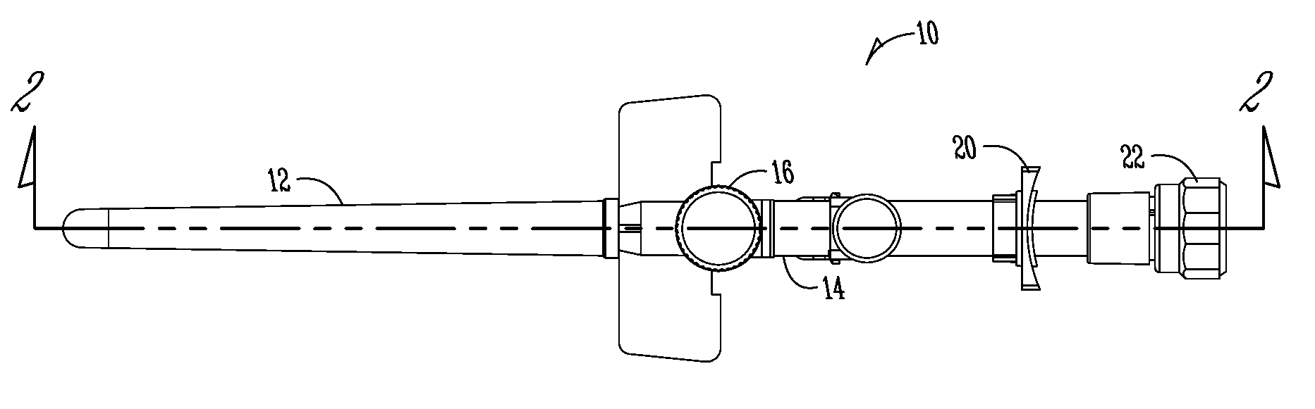
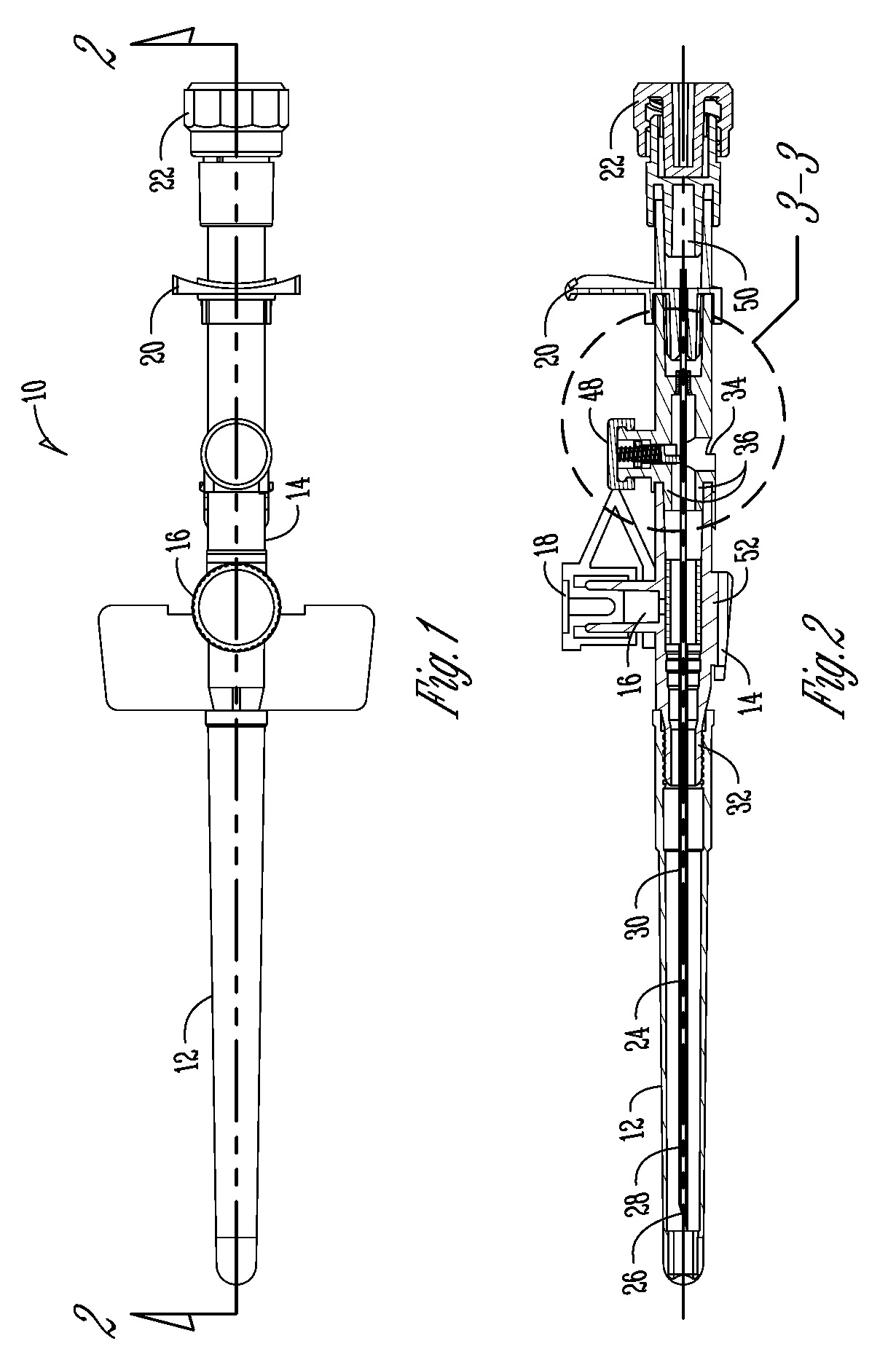
[0031]Referring to FIG. 1, an intravenous (IV) catheter apparatus 10 of the present invention is shown. It comprises of needle cover 12, wing housing 14, port 16 in unitary assembly with the wing housing 14 and needle hub 20. Luer lock 22 is removably attached to wing housing 14. The needle cover 12 covers the needle 24 (shown in FIG. 2). The needle hub 20 can be detached from the wing housing 14 such that the assembly of needle 24, needle hub 20 and luer lock 22 can be separated from the assembly of wing housing 14 and port 16, such as shown in FIG. 8A.

[0032]FIG. 2 is a cross sectional view of the IV catheter apparatus 10 which depicts a needle 24 extending from needle hub 20 through the wing housing 14 and ending at the needle tip 26 under the needle cover 12.

[0033]The needle 24 is hollow and the needle tip 26 is cut diagonally. There is needle flaring 28 which increases the diameter of the needle 24 near the needle tip 26. Surrounding the needle 24 is a catheter 30 which is attac...


PUM


Abstract

A safety device for the needle of intravenous catheter apparatus comprising of a tip blocker which blocks the needle tip, a spring assembled in compressed state held by a disc inside the groove of the tip blocker which pushes the tip blocker downwards and a bush fitted in the needle passageway which does not allow the needle to come out of the safety device. The safety device is capable of locking inside it and covering the needle tip so that the needle of intravenous catheter apparatus can be disposed of safely.

Description

CROSS-REFERENCE TO RELATED APPLICATIONS[0001]This application claims priority under 35 U.S.C. §119 of a provisional application Ser. No. 60 / 804,214 filed Jun. 8, 2006, which application is hereby incorporated by reference in its entirety.FIELD OF INVENTION[0002]The present invention relates to a safety device for the needle of an intravenous catheter apparatus. More particularly this invention relates to a safety device fitted to an intravenous catheter apparatus which covers the needle tip after use, prior to the needle being disposed of, thereby preventing accidental pricking of the used needle of the intravenous catheter apparatus by medical professionals, people in charge of disposal of hospital waste and anybody who accidentally or intentionally handles or tries to dispose of the intravenous catheter apparatus.BACKGROUND OF INVENTION[0003]The intravenous catheter apparatus is used to inject medicines, glucose and other nourishment, in liquid form, into the blood stream of patie...

Claims


Application Information

Patent Timeline
Patent Type & Authority Patents(United States)
IPC IPC(8): A61M5/178A61M5/00
CPCA61M25/0618A61M25/0637A61M5/3273A61M2005/325
Inventor BAID, RISHI
Owner BAID RISHI
Why Eureka
Try Eureka