Display apparatus

a display apparatus and self-luminous technology, applied in the direction of instruments, discharge tubes luminescnet screens, static indicating devices, etc., can solve the problems of difficult to accurately align electrodes of substrates and electrically connect electrodes to each other, and the efficiency is considerably poor. , to achieve the effect of improving the yield of the stacking step between the drive circuit substrate and the light-emitting substra

Active Publication Date: 2012-08-07
JOLED INC
View PDF11 Cites 4 Cited by
  • Summary
  • Abstract
  • Description
  • Claims
  • Application Information

AI Technical Summary

Benefits of technology

[0008]It is an object of the present invention to provide a display apparatus configured to stack a drive circuit substrate and a light-emitting substrate, electrodes of the substrates are accurately aligned to be electrically connected to each other. Furthermore, it is another object of the present invention to provide a display apparatus having a long emission lifetime and a small fluctuation in display.
[0039]As described above, in the display apparatus according to the present invention, an intermediate electrode of the light-emitting substrate is arranged to be elongated in parallel to or perpendicular to a longitudinal direction of pixel electrodes in a stacked plane between the drive circuit substrate and the light-emitting substrate. In this manner, even though positions of the connection electrodes of the drive circuit substrate are slightly misaligned, a range of misalignment along the longitudinal direction of the intermediate electrode can be allowed. Therefore, a margin can be given to alignment accuracy in stacking between the drive circuit substrate and the light-emitting substrate. In this manner, a yield of the stacking step between the drive circuit substrate and the light-emitting substrate can be improved.

Problems solved by technology

As in the former, when the active matrix substrate and the counter substrate are to be fabricated to be sequentially stacked, if the steps to manufacture substrate parts are different in yield from each other, efficiency is considerably poor because the efficiency depends on the step having a low yield.
On the other hand, when the active matrix substrate (also called a “drive circuit substrate”) and the counter substrate (also called a “light-emitting substrate”) are to be fabricated to be stacked to each other, in comparison with the fabrication performed by sequentially stacking the substrates, the efficiency is not easily influenced by the step having a low yield.
However, it is very difficult to accurately align electrodes of the substrates and electrically connect the electrodes to each other.

Method used


Image

  • Display apparatus
  • Display apparatus
  • Display apparatus

Examples


first embodiment

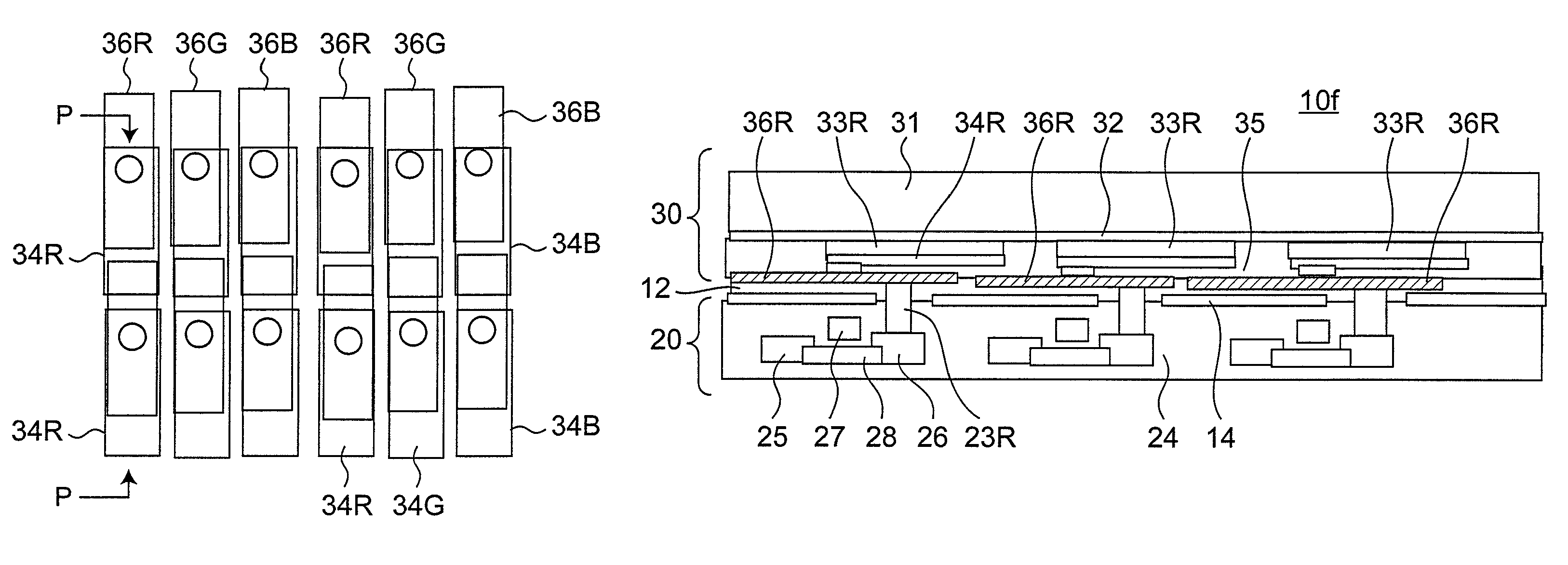
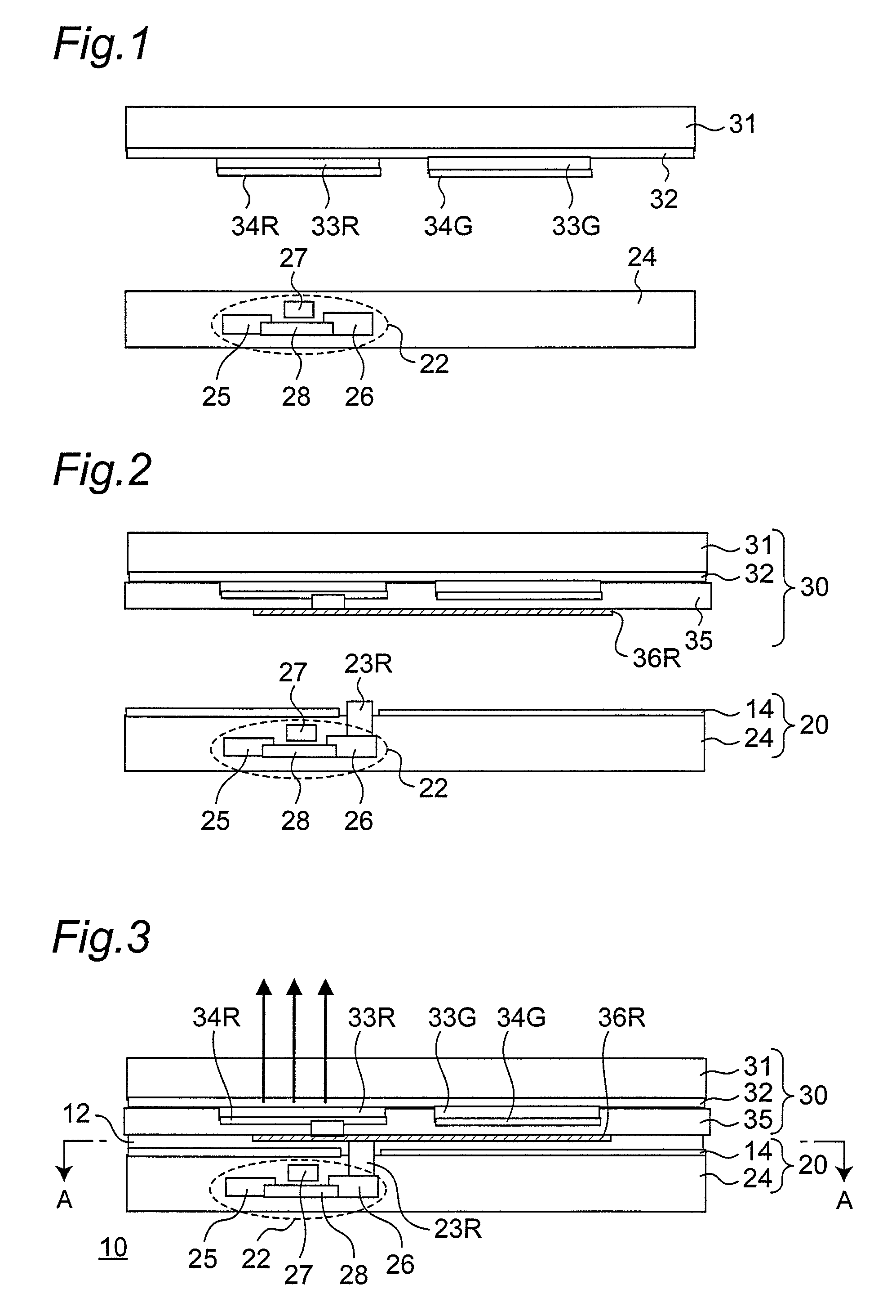
[0057]FIG. 3 is a schematic sectional view showing an entire configuration of a display apparatus 10 according to a first embodiment. The display apparatus 10 includes a drive circuit substrate 20 having a drive circuit 22 and a light-emitting substrate 30 which is arranged to face the drive circuit substrate 20 and which has a light-emitting unit including a common electrode 32, a light-emitting layer 33, and a pixel electrode 34. As a characteristic feature of the display apparatus 10, the pixel electrode 34 is further connected to an intermediate electrode 36. The drive circuit substrate 20 and the light-emitting substrate 30 are stacked to each other by an insulating adhesive layer 12. On the stacked plane, a connection electrode 23 of a circuit substrate 20 is connected to the intermediate electrode 36 of the light-emitting substrate 30. On the drive circuit substrate 20 side of the stacked plane, a ground electrode 14 which is developed in an in-plane direction and which has a...

second embodiment

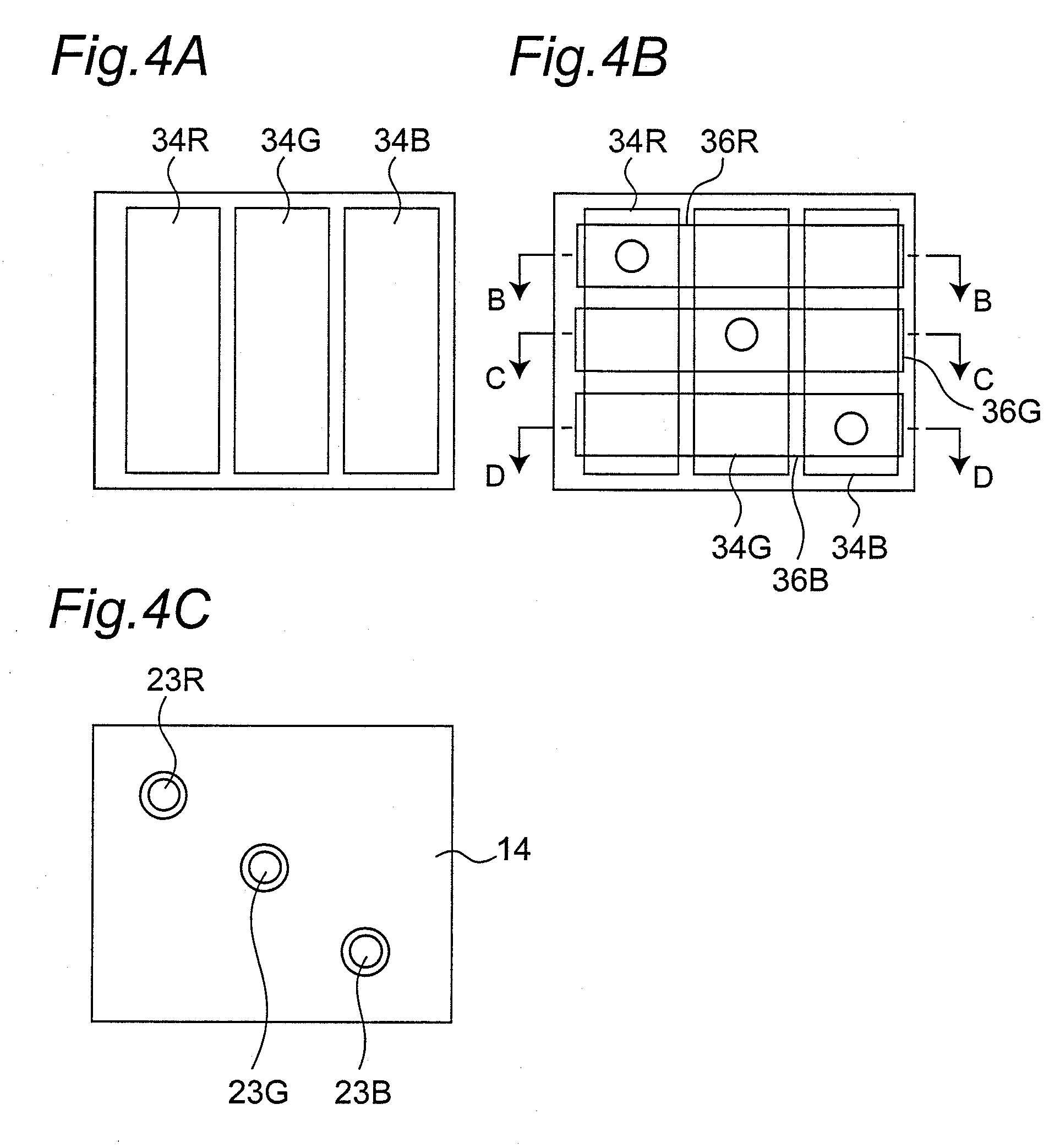
[0092]FIG. 7A is a schematic sectional view showing an overall configuration of a display apparatus 10a according to a second embodiment, FIG. 7B is a sectional view along an E-E line in FIG. 7A, and FIG. 7C is a sectional view along an F-F line in FIG. 7A. As a characteristic feature of this display apparatus 10a, as shown in FIG. 7C, the intermediate electrodes 36R, 36G, and 36B has areas larger than the areas of the pixel electrodes 34R, 34G, and 34B, respectively.

[0093]On the other hand, in the conventional techniques described in Japanese Unexamined Patent Publication No. 2004-6337 and Japanese Unexamined Patent Publication No. 2005-208423, a connection electrode and a pixel electrode on a drive circuit substrate side are directly in contact with each other without an intermediate electrode.

[0094]In contrast to this, in the display apparatus 10a according to the second embodiment, the intermediate electrode 36 having an area larger than pixel electrode 34 is arranged, and the p...

third embodiment

[0096]FIG. 8A is a schematic sectional view showing an entire configuration of a display apparatus 10b according to the third embodiment, FIG. 8B is a sectional view along a G-G line in FIG. 8A, and FIG. 8C is a sectional view along an H-H line in FIG. 8A. As a characteristic feature of the display apparatus 10b, the sizes of the intermediate electrodes 36R, 36G, and 36B are set in the order of sizes of the connection electrodes 23R, 23G, and 23B. According to the configuration, when sizes of drive power supplies change depending on the colors, and when sizes of connection electrodes change depending on colors, a margin of alignment between the drive circuit substrate 20 and the light-emitting substrate 30 can be maximally obtained, and the connection electrode 23 and the intermediate electrode 36 can be reliably in contact with each other.


PUM


Abstract

There is provided a display apparatus configured by stacking a drive circuit substrate and a light-emitting substrate. Electrodes of the substrates are accurately aligned to be electrically connected to each other. A display apparatus is configured by stacking a drive circuit substrate having a drive circuit and a light-emitting substrate having a light-emitting unit including a pixel electrode to cause the drive circuit substrate and the light-emitting substrate to face each other, wherein on a stacked plane between the drive circuit substrate and the light-emitting substrate, an intermediate electrode connected to the light-emitting unit of the light-emitting substrate and a connection electrode connected to the drive circuit and the drive circuit substrate are electrically connected to each other, and the intermediate electrode is elongated in a direction parallel to or perpendicular to a longitudinal direction of the pixel electrode on the stacked plane.

Description

BACKGROUND OF THE INVENTION[0001]1. Field of the Invention[0002]The present invention relates to a self-luminous display apparatus and, more particularly, to an electro-luminous display apparatus in which a light-emitting substrate having a light-emitting unit including an electro-luminous layer and an active matrix substrate having a drive circuit such as a TFT are stacked to each other.[0003]2. Description of the Related Art[0004]In OA equipment, AV equipment, mobile terminals, and the like, electro-luminous display apparatuses are used as display apparatuses which can achieve high-quality displays, small thicknesses, and low power consumptions. One of the electro-luminous apparatuses includes an organic electro-luminescence (EL) display apparatus using an organic electro-luminous layer. In the organic electro-luminescence display apparatus, a technique which drives a plurality of organic EL elements arranged in the form of an X-Y matrix by a simple matrix drive (passive drive) to...

Claims


Application Information

Patent Timeline
Patent Type & Authority Patents(United States)
IPC IPC(8): H01J1/62
CPCG09G3/3225H01L27/3253G09G2300/023G09G2300/0426G09G2300/0443G09G2300/0452H01L27/3211H10K59/1275H10K59/35
Inventor HIGASHIDA, TAKAAKIIWANE, YOSHIENAGAI, HISAONISHIKAWA, KAZUHIROHAYATA, HIROSHI
Owner JOLED INC
Why Eureka
Try Eureka