
Organic electroluminescent element

a technology of electroluminescent elements and organic el elements, which is applied in the field of organic electroluminescent elements, can solve the problems of insufficient light emission efficiency, lifetime and stable chromaticity, and the demand for emission color stability is particularly severe, and achieves high light emission efficiency, long emission lifetime, and high light emission efficiency.

Active Publication Date: 2017-10-03
KONICA MINOLTA INC
View PDF15 Cites 0 Cited by
  • Summary
  • Abstract
  • Description
  • Claims
  • Application Information

AI Technical Summary

Benefits of technology

The present invention is about an organic electroluminescent element that can stay bright and emits light with high efficiency for a long time.

Problems solved by technology

Although such system has significantly high potential, quite unlike the organic EL devices utilizing fluorescence emission, the organic EL devices utilizing phosphorescence emission has an important technical problem which is to control the position of the emission center, in particular to achieve recombination and stable light-emission inside the light emitting layer, from the viewpoint of efficiency and lifetime of the elements.
In applications to illumination light sources, the demand for the stability of the emission color is especially severe.
Unfortunately, the organic EL element composed of metal complexes as described in Patent Literature 3 is still insufficient in light emitting efficiency, lifetime and stable chromaticity.

Method used

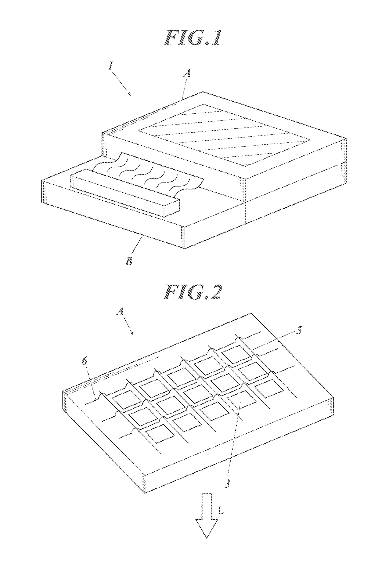
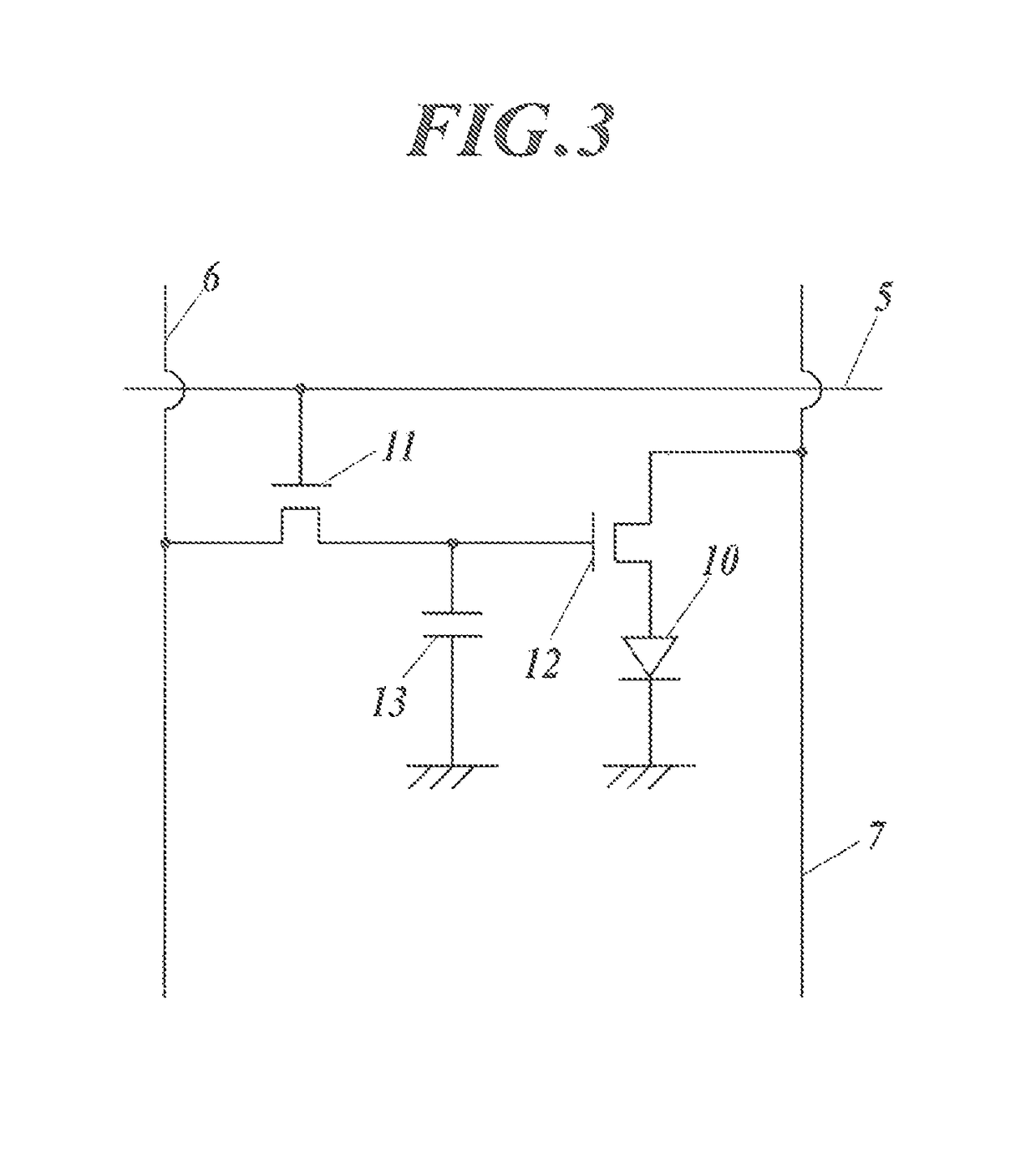
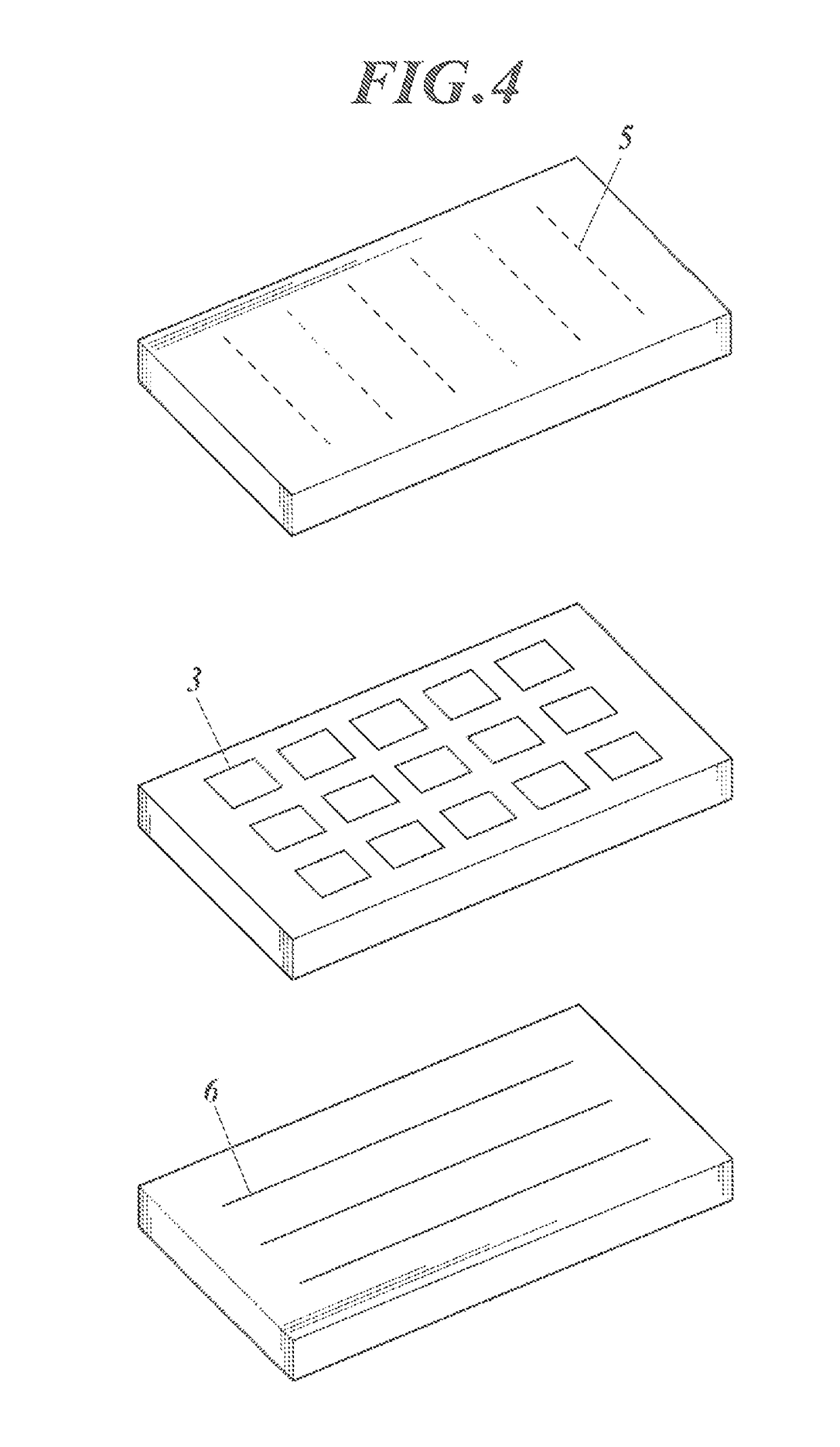

Image

  • Organic electroluminescent element
  • Organic electroluminescent element
  • Organic electroluminescent element

Examples


example 1

>

[0320]A substrate (NA45 available from NH TECHNOGLASS CORPORATION), which was a glass substrate of 100 mm by 100 mm by 1.1 mm thick provided with an anode of a 100 nm thick ITO (indium tin oxide) film thereon, was subjected to patterning. The resulting transparent supporting substrate provided with the transparent ITO electrode was cleaned in isopropyl alcohol with an ultrasonic cleaner, dried with nitrogen gas, and then exposed to UV / ozone for five minutes.

[0321]The transparent supporting substrate was fixed on the substrate holder in a commercially available vacuum deposition apparatus. 200 mg of HT-30 was placed in a resistively heated molybdenum boat, 200 mg of HT-2 was placed in another resistively heated molybdenum boat, 200 mg of compound 2-45 was placed in another resistively heated molybdenum boat, 200 mg of HS-1 was placed in another resistively heated molybdenum boat, 200 mg of DP-1 was placed in another resistively heated molybdenum boat, 200 mg of compound 3-7 was plac...

example 2

>

[0342]A substrate (NA45 available from NH TECHNOGLASS CORPORATION), which was a glass substrate of 100 mm by 100 mm by 1.1 mm thick provided with an anode of a 100 nm thick ITO (indium tin oxide) film thereon, was subjected to patterning. The resulting transparent supporting substrate provided with the transparent ITO electrode was cleaned in isopropyl alcohol with an ultrasonic cleaner, dried with nitrogen gas, and then exposed to UV / ozone for five minutes.

[0343]The transparent supporting substrate was fixed on the substrate holder in a commercially available vacuum deposition apparatus. 200 mg of HT-30 was placed in a resistively heated molybdenum boat, 200 mg of HT-2 was placed in another resistively heated molybdenum boat, compound 2-45 was placed in another resistively heated molybdenum boat, 200 mg of HS-1 was placed in another resistively heated molybdenum boat, 200 mg of DP-1 was placed in another resistively heated molybdenum boat, 200 mg of cGD-1 was placed in another res...

example 3

>

[0355]A substrate (NA45 available from NH TECHNOGLASS CORPORATION), which was a glass substrate of 100 mm by 100 mm by 1.1 mm thick provided with an anode formed of a 100 nm thick ITO (indium tin oxide) film thereon, was subjected to patterning. The resulting transparent supporting substrate provided with the transparent ITO electrode was cleaned in isopropyl alcohol with an ultrasonic cleaner, dried with nitrogen gas, and then subjected to UV / ozone cleaning for five minutes.

[0356]The transparent supporting substrate was fixed on the substrate holder in a commercially available vacuum deposition apparatus. 200 mg of HT-30 was placed in a resistively heated molybdenum boat, 200 mg of HT-2 was placed in another resistively heated molybdenum boat, 200 mg of compound 2-45 was placed in another resistively heated molybdenum boat, 200 mg of HS-1 was placed in another resistively heated molybdenum boat, 200 mg of DP-1 was placed in another resistively heated molybdenum boat, 200 mg of HS-...


PUM

PropertyMeasurementUnit
atomic numberaaaaaaaaaa
thicknessaaaaaaaaaa
thicknessaaaaaaaaaa

Abstract

An organic electroluminescent element includes a hole injection layer (HI), a first hole transport layer (HT1), a second hole transport layer (HT2), and a light-emitting layer containing a host compound (H) and a phosphorescence emitting dopant compound (D), which are laminated in this order, between and an anode and a cathode. The phosphorescence emitting dopant compound has a partial structure represented by Formula (1):The “highest occupied molecular orbital” HOMO of the second hole transport layer satisfies the expression: −5.4<HOMO (HT2)<−4.8; and the relationship of triplet excitation energies (T1) between the phosphorescence emitting dopant compound and a hole transport material contained in the second hole transport layer satisfies the expression: T1 (HT2)−T1 (D)>0.1.

Description

CROSS-REFERENCE TO RELATED APPLICATION[0001]This Application is a 371 of PCT / JP2012 / 075508 filed on Oct. 2, 2012 which, in turn, claimed the priority of Japanese Patent Application No. JP2011-231404 filed on Oct. 21, 2011 both applications are incorporated herein by reference.TECHNICAL FIELD[0002]The present invention relates to an organic electroluminescent element.BACKGROUND ART[0003]An organic electroluminescent element (hereinafter, also referred to as an organic EL element) has a structure including a light emitting layer, which is composed of a light emitting compound, and a cathode and an anode which sandwich the light emitting layer. The organic EL element emits light (fluorescence or phosphorescence) generated as a result of deactivation of excitons formed by the recombination of holes and electrons injected in the light emitting layer from the anode and the cathode, respectively, in an applied electric field. The organic EL element is an entire solid element including a la...

Claims


Application Information

Patent Timeline
Patent Type & Authority Patents(United States)
IPC IPC(8): H01L51/54H01L51/50C09K11/06H05B33/10H01L51/00H10K99/00
CPCH01L51/5064C09K11/06H01L51/0072H01L51/0073H01L51/0085H01L51/5004H01L51/5016H01L51/5072H01L51/5088H05B33/10C09K2211/1007C09K2211/1011C09K2211/1029C09K2211/1033C09K2211/1044C09K2211/1059C09K2211/1088C09K2211/1092C09K2211/185H01L51/0059H01L51/0094H01L2251/55H10K85/631H10K85/6572H10K85/342H10K85/40H10K50/11H10K2101/40H10K2101/10H10K50/156H10K50/16H10K50/17H10K85/6574H10K2101/00
Inventor TANI, KUNIOKATOH, EISAKUITO, HIROTOHIYAMA, KUNIMASA
Owner KONICA MINOLTA INC
Learn More