
Organic electroluminescent member and method for producing organic electroluminescent element

a technology of organic electroluminescence and organic electroluminescence, which is applied in the direction of thermoelectric devices, solid-state devices, and semiconductor/solid-state device details, etc., can solve the problems of deterioration of efficiency and lifetime, deterioration of performance, and difficulty in handling, and achieve excellent thermal stability, low voltage, and high luminance

Active Publication Date: 2014-10-14
MERCK PATENT GMBH
View PDF15 Cites 0 Cited by
  • Summary
  • Abstract
  • Description
  • Claims
  • Application Information

AI Technical Summary

Benefits of technology

The present invention provides an organic EL member that is stable, can be operated at low voltage, and has high brightness and long emission lifetime. Additionally, a method for producing an organic electroluminescence element that utilizes this member is also provided.

Problems solved by technology

However, an alkali metal and an alkali earth metal, in particular, an alkali metal has a high reactivity, and there was difficulty in handling at the time of production of an organic EL element and in stability after the production of an organic EL element.
However, although it improves to some extent a luminescent property and a lifetime, still it is insufficient.
On the other hand, it has problems that deterioration of efficiency and deterioration of lifetime will occur under a high temperature condition, or during a prolonged storage time.
Although it can improve, to some extent, deterioration of performance under a high temperature condition, or during a prolonged storage time, still it is insufficient.
It is still difficult for a current status to reconcile the performance and the stability of an organic EL element.

Method used


Image

  • Organic electroluminescent member and method for producing organic electroluminescent element
  • Organic electroluminescent member and method for producing organic electroluminescent element
  • Organic electroluminescent member and method for producing organic electroluminescent element

Examples


example 1

Preparation of Organic EL Member

[Preparation of Organic EL Member 101]

(Preparation of Anode)

[0104]An anode was prepared by making patterning to a glass substrate (NA45 produced by NH Techno Glass Corp.) on which a 100 nm film of ITO (indium tin oxide) was formed. Thereafter, the above transparent support substrate provided with the ITO transparent electrode was subjected to ultrasonic washing with isopropyl alcohol, followed by drying with desiccated nitrogen gas, and was subjected to UV ozone washing for 5 minutes.

(Preparation of Hole Transport Layer)

[0105]On the transparent support substrate thus prepared was applied a 50% solution of poly(3,4-ethylenedioxythiphene)-polystyrene sulfonate (abbreviation: PEDOT / PSS, Baytron P AI 4083 made by Bayer AG.) diluted with water by using a spin coating method at 3,000 rpm for 30 seconds to form a film, and then, it was kept at 150° C. for 30 minutes. A hole transport layer having a thickness of 60 nm was thus prepared.

(Preparation of Light E...

example 2

Preparation of Organic EL Member

[Preparation of Organic EL Member 201]

[0124]Organic EL member 201 was prepared in the same manner as preparation of Organic EL member 107 described in Example 1, except performing the following change after formation of a light emitting layer. Alq3 (glass transition temperature, 128 C°), potassium fluoride, and sodium fluoride each were placed in a tantalum resistance heating boat, and aluminium was placed in a tungsten resistance heating boat. They were fitted in a vacuum deposition apparatus. The substrate having been prepared until the light emitting layer was transferred in the vacuum deposition apparatus without exposing to the air. Subsequently, after reducing the pressure of the vacuum tank to 5×10⁻⁵ Pa, the heating boat containing Alq3 was heated via application of electric current at a vapor deposition rate of 0.15 nm / second to produce a layer having a thickness of 40 nm. Thus an electron transport layer was prepared. Then, the heating boat c...

example 3

Preparation of Organic EL Member

[Preparation of Organic EL Member 301]

[0128]Organic EL member 301 was prepared in the same manner as preparation of Organic EL member 201 described in Example 2, except that the sample was heated at 100° C. for 30 minutes after formation of a cathode.

[Preparation of Organic EL Member 302]

[0129]Organic EL member 302 was prepared in the same manner as preparation of Organic EL member 201 described in Example 2, except that the following change was made. The sample was transferred under a nitrogen gas atmosphere after formation of a second electron injection layer, and it was heated at 100° C. for 30 minutes. Then, it was restored in the vacuum deposition apparatus and aluminium was vapor deposited to have a thickness of 100 nm to form a cathode.

>

[0130]The prepared Organic EL members 301 and 302 described above were transferred in a nitrogen gas (grade: G1) atmosphere in the same manner as described in Example 1. After leaving them at 40° C. for 12 hours...


PUM


Abstract

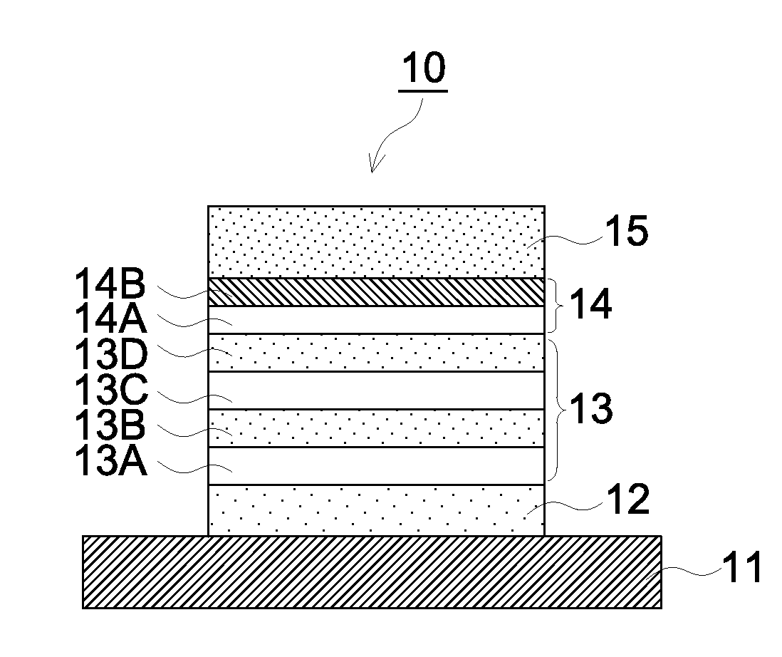
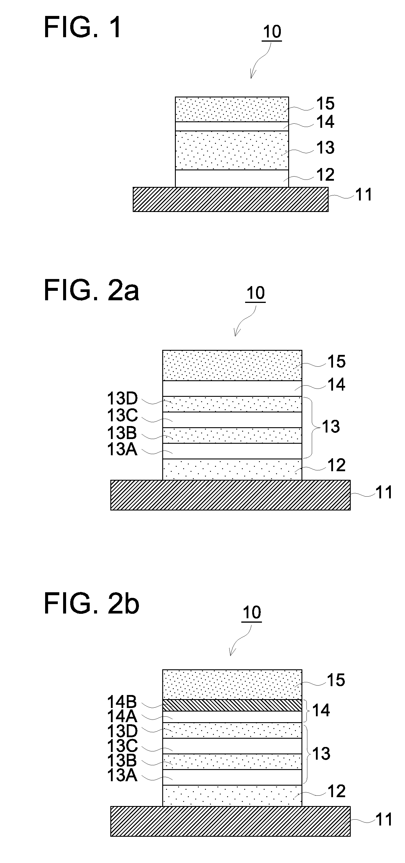
An organic electroluminescent member comprising: a positive electrode and a negative electrode on a substrate: multiple organic layers which include at least a positive hole transport layer, a light-emitting layer and an electron transport layer, and which are arranged between the positive electrode and the negative electrode; and an electron injection layer arranged between the electron transport layer and the negative electrode. The electron injection layer is formed from at least one selected from the group consisting of alkali metals and compounds containing alkali metals having a melting point of less than 90° C., and at least one selected from the group consisting of alkali metals, alkaline earth metals, compounds containing alkali metals, and compounds containing.

Description

CROSS REFERENCE TO RELATED APPLICATIONS[0001]This is a U.S. national stage of application No. PCT / JP2011 / 051878, filed on 31 Jan. 2011. Priority under 35 U.S.C. §119(a) and 35 U.S.C. §365(b) is claimed from Japanese Application No. 2010-051518, filed 9 Mar. 2010, the disclosure of which are also incorporated herein by reference.TECHNICAL FIELD[0002]The present invention relates to a novel organic electroluminescence member, and a method for producing an organic electroluminescence element using the same.BACKGROUND[0003]Conventionally, it is known an electroluminescence display (hereinafter, referred to as an ELD) as an emission type electronic display device. As a composing element of an ELD, there are cited an inorganic electroluminescence element (hereinafter, referred to as an inorganic EL element) and an organic electroluminescence element (hereinafter, referred to as an organic EL element).[0004]An inorganic EL element has been utilized mainly as a flat light source, however, i...

Claims


Application Information

Patent Timeline
Patent Type & Authority Patents(United States)
IPC IPC(8): H01L29/08H10K99/00
CPCH01L51/5092H01L51/0081H01L51/002H10K71/30H10K85/324H10K50/171
Inventor ARAI, KENJIIWASAKI, TOSHIHIKO
Owner MERCK PATENT GMBH
Learn More