
Four-channel color filter array interpolation

a color filter array and interpolation technology, applied in the field of four, can solve the problems of reducing the overall amount of light, reducing the sensitivity to light, and pixel value becoming more susceptible to noise from non-imaging sources, so as to reduce the color noise in the image, improve the color spatial resolution of the image, and increase the spectral bandwidth of the color pixels.

Active Publication Date: 2012-08-07
OMNIVISION TECH INC
View PDF103 Cites 4 Cited by
  • Summary
  • Abstract
  • Description
  • Claims
  • Application Information

AI Technical Summary

Benefits of technology

[0016]An advantage of the present invention is that the color spatial resolution of the image is improved without the need of increasing the percentage of color pixels with respect to panchromatic pixels within the sensor.
[0017]A further advantage of the present invention is that a reduction of color noise in the image is realized without the need for increasing the spectral bandwidth of the color pixels with the correspondingly reduction of color fidelity of the image.

Problems solved by technology

This has the side effect of reducing the overall amount of light that reaches the pixel and, therefore, reduces its sensitivity to light.
As a consequence, the pixel value becomes more susceptible to noise from non-imaging sources, e.g., thermal noise.
However, this comes with the side effect of reducing color fidelity.
The problem with Frame is that the resulting color spatial resolution is too low to produce all but the lowest frequency color details in the image.
The use of solely linear interpolation methods (such as bilinear interpolation) strongly limits the spatial resolution of the interpolated image.
However, the yellow and cyan pixels do not conform to the patterns of either FIG. 14B or FIG. 14C.
The same difficulties exist with the other patterns taught by Tanaka et al.

Method used


Image

  • Four-channel color filter array interpolation
  • Four-channel color filter array interpolation
  • Four-channel color filter array interpolation

Examples


Embodiment Construction

[0035]In the following description, a preferred embodiment of the present invention will be described in terms that would ordinarily be implemented as a software program. Those skilled in the art will readily recognize that the equivalent of such software can also be constructed in hardware. Because image manipulation algorithms and systems are well known, the present description will be directed in particular to algorithms and systems forming part of, or cooperating more directly with, the system and method in accordance with the present invention. Other aspects of such algorithms and systems, and hardware or software for producing and otherwise processing the image signals involved therewith, not specifically shown or described herein, can be selected from such systems, algorithms, components and elements known in the art. Given the system as described according to the invention in the following materials, software not specifically shown, suggested or described herein that is usef...


PUM


Abstract

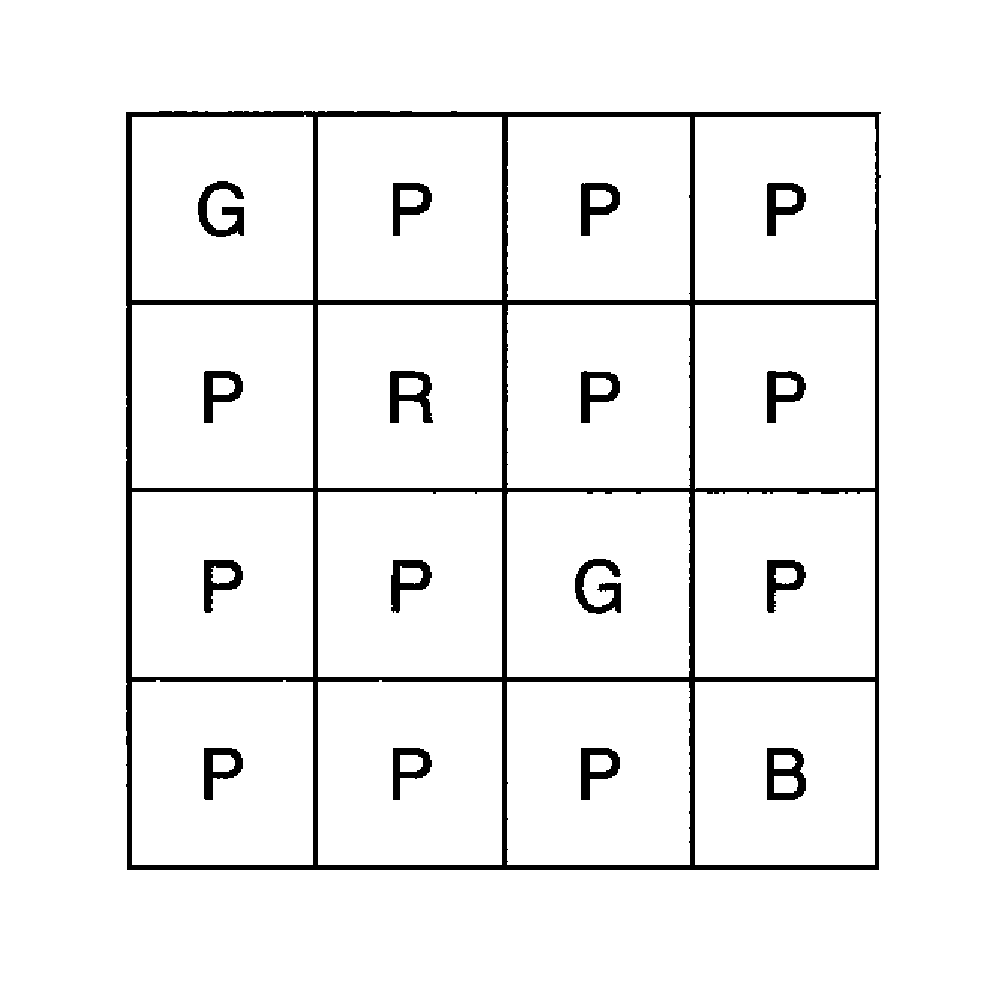
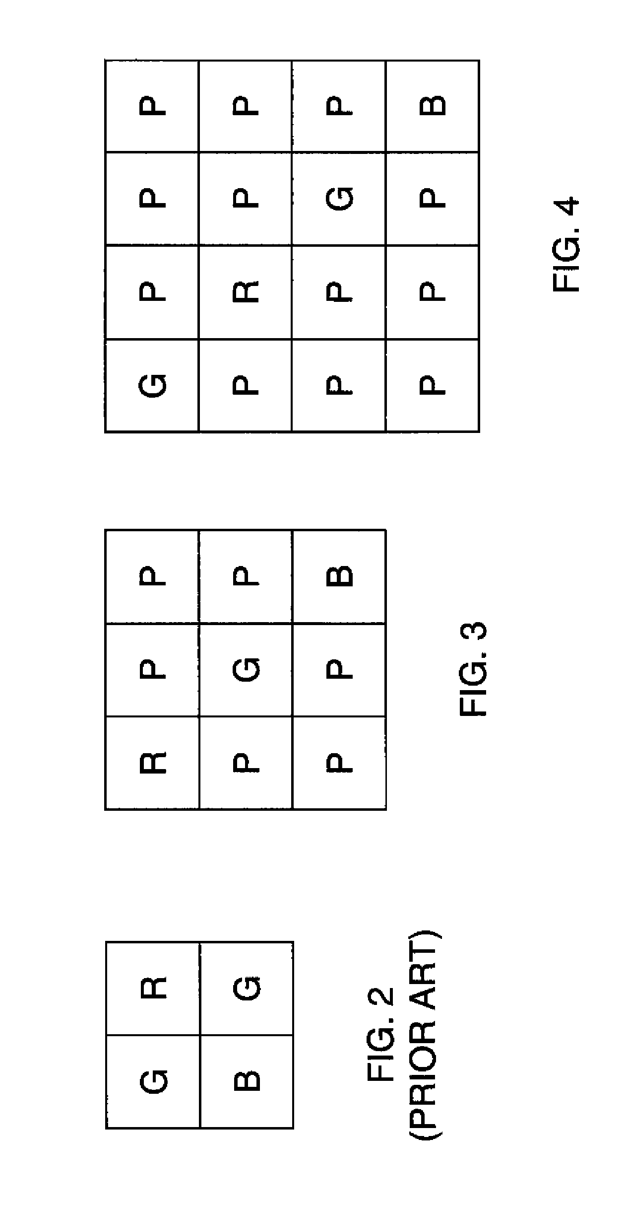
A method of forming a full-color output image from a color filter array image having a plurality of color pixels having at least two different color responses and panchromatic pixels, comprising capturing a color filter array image using an image sensor including panchromatic pixels and color pixels having at least two different color responses, the pixels being arranged in a repeating pattern having a square minimal repeating unit having at least three rows and three columns, the color pixels being arranged along one of the diagonals of the minimal repeating unit, and all other pixels being panchromatic pixels; computing an interpolated panchromatic image from the color filter array image; computing an interpolated color image from the color filter array image; and forming the full color output image from the interpolated panchromatic image and the interpolated color image.

Description

CROSS REFERENCE TO RELATED APPLICATIONS[0001]Reference is made to commonly assigned U.S. application Ser. No. 12 / 401,002, filed Mar. 10, 2009 entitled CFA IMAGE WITH SYNTHETIC PANCHROMATIC IMAGE by Kumar et al., commonly assigned U.S. application Ser. No. 12 / 412,429, filed Mar. 27, 2009 entitled PRODUCING FULL-COLOR IMAGE USING CFA IMAGE by Kumar et al., commonly assigned U.S. application Ser. No. 12 / 423,839 filed Apr. 15, 2009 entitled PRODUCING FULL-COLOR IMAGE WITH REDUCED MOTION BLUR by Kumar et al., and commonly assigned U.S. application Ser. No. 12 / 472,563 filed May 27, 2009 entitled FOUR-CHANNEL COLOR FILTER ARRAY PATTERN by James E. Adams Jr., the disclosures of which are incorporated herein by reference.FIELD OF THE INVENTION[0002]The present invention relates to producing a full-color image with improved spatial resolution from a color filter array image having color channels and a panchromatic channel.BACKGROUND OF THE INVENTION[0003]A single-sensor digital camera employs...

Claims


Application Information

Patent Timeline
Patent Type & Authority Patents(United States)
IPC IPC(8): H04N3/14
CPCH04N9/045H04N9/07H04N2101/00H04N25/133H04N25/135H04N23/843H04N23/12
Inventor ADAMS, JR., JAMES E.KUMAR, MRITYUNJAYPILLMAN, BRUCE H.HAMILTON, JAMES A.
Owner OMNIVISION TECH INC
Learn More