Output shaft speed sensor based anti-lock braking system

a technology of output shaft speed and anti-locking system, which is applied in the direction of braking system, process and machine control, instruments, etc., can solve the problems of no mechanism for the abs to be the cause of powertrain control module (pcm) or oss sensor failur

Active Publication Date: 2012-08-07
FORD GLOBAL TECH LLC
View PDF7 Cites 6 Cited by
  • Summary
  • Abstract
  • Description
  • Claims
  • Application Information

AI Technical Summary

Problems solved by technology

Rear wheel speed sensors have historically been a significant source of anti-lock braking system (ABS) warranty, because of their operation in harsh operating environments, namely, exposure to high heat and accelerations of the sensor and wire harness on the axle and placement in high splash zones.
Further, they become problematic because of damage from aftermarket body builders.
In contrast, there is no mechanism for the ABS to be the cause of Powertrain Control Module (PCM) or OSS sensor failures.

Method used


Image

  • Output shaft speed sensor based anti-lock braking system
  • Output shaft speed sensor based anti-lock braking system
  • Output shaft speed sensor based anti-lock braking system

Examples


Embodiment Construction

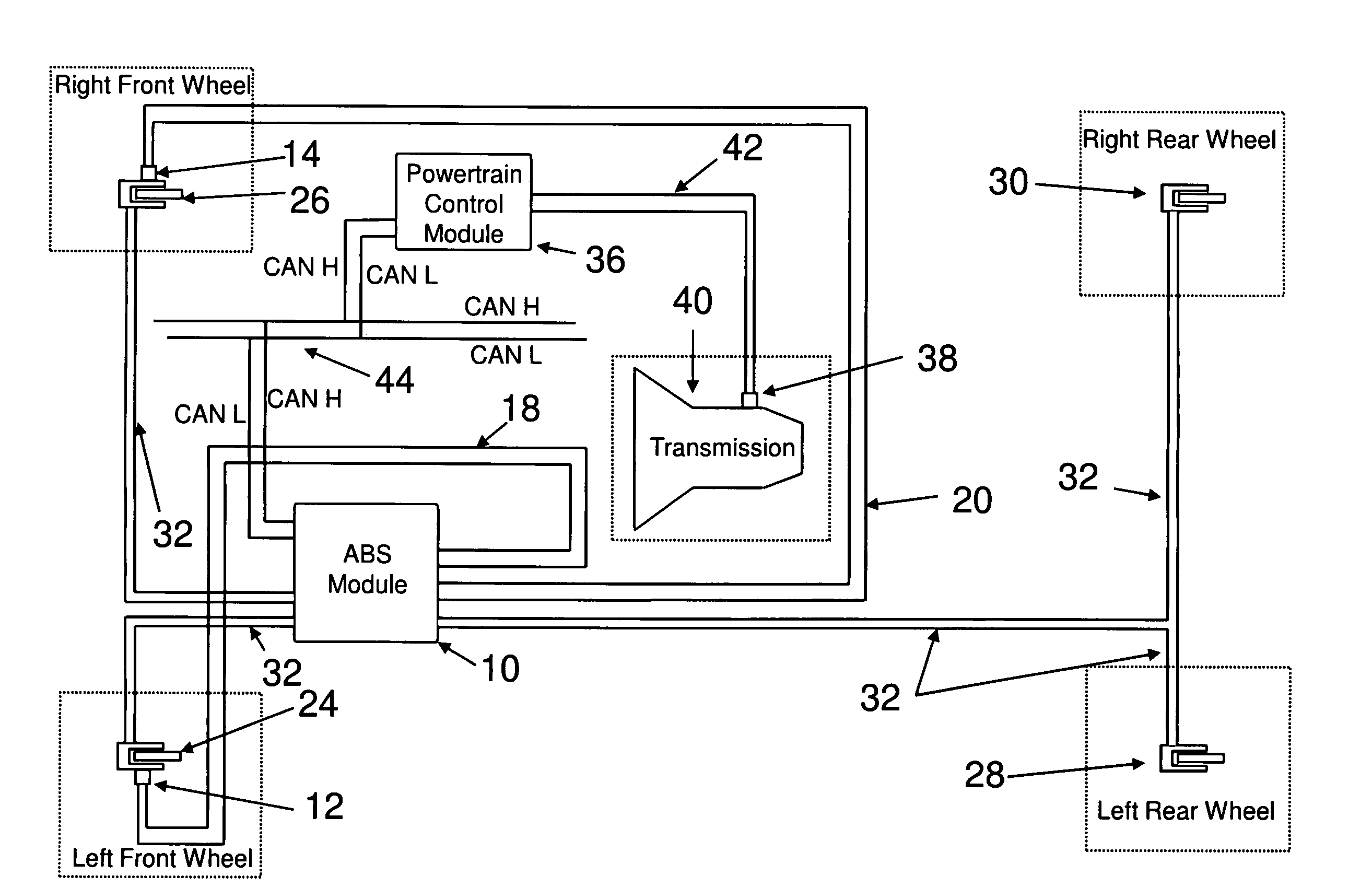
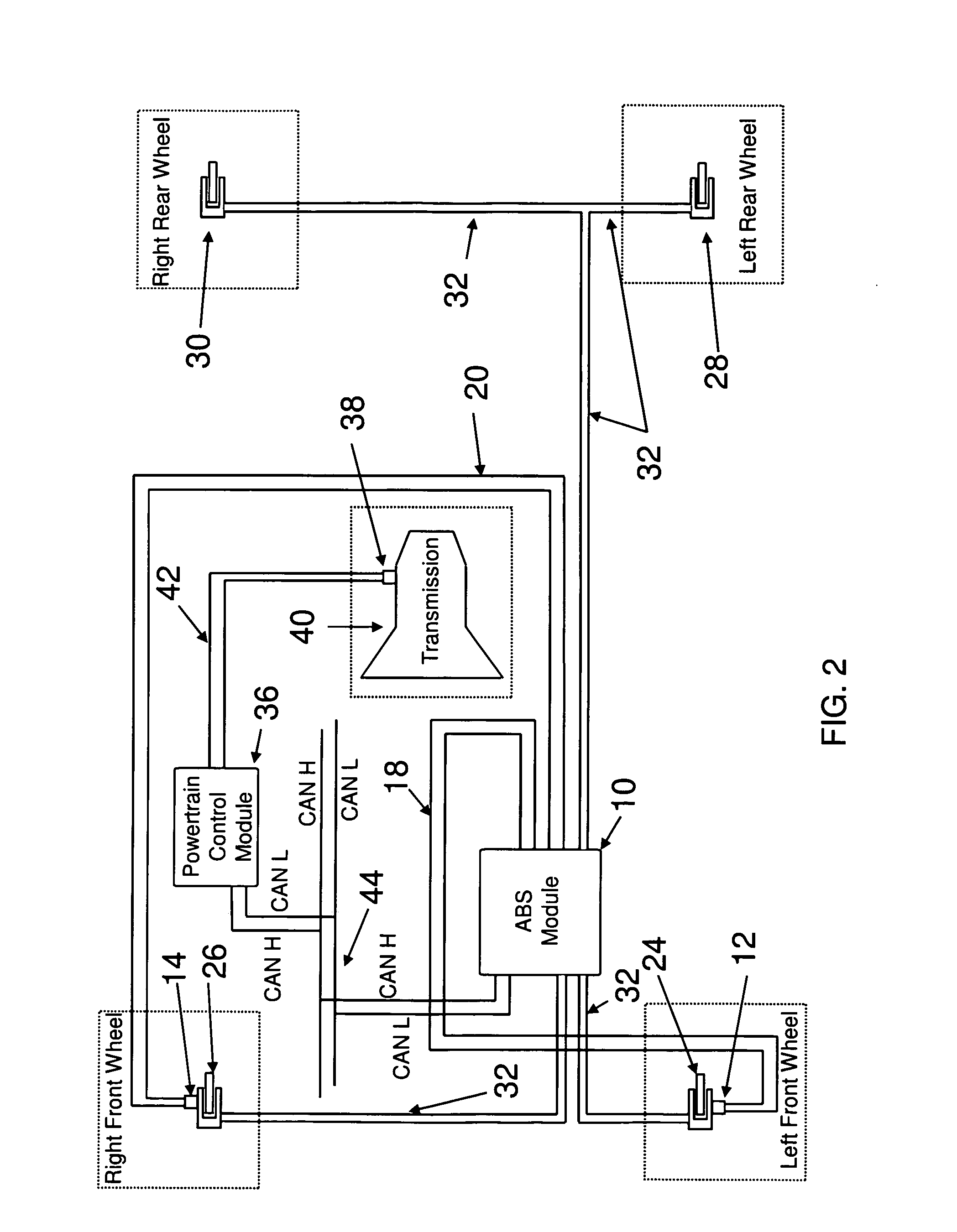
[0012]The inventors use the output shaft speed (OSS) signal, in lieu of the differential speed sensor (DSS) signal, to determine the rear wheel speeds, hence eliminating the need for the DSS. The OSS signal conventionally is calculated and used internally by the vehicle PCM (Powertrain Control Module). The inventors modified the CAN message list to allow this signal to also be sent to the ABS module by the PCM. This raw signal is filtered and then used by the ABS module for the rear wheel speeds. The invention makes use of this OSS signal / sensor instead of a dedicated rear wheel speed sensor such as the DSS, and allows for the elimination of the cost / assembly / wiring / components of the DSS.

[0013]Such a modified OSS signal / sensor enhances ABS reliability over the conventional ABS system that relies on the DSS to provide rear wheel speed information. Indeed, only the loss of the CAN bus leads to the loss of ABS. There is no longer loss of the ABS due to failure with the DSS. Further, th...


PUM


Abstract

An anti-lock braking system (ABS) calculates driven wheel speed without any sensors on the driven axle assembly. A powertrain control module (PCM) receives signals from an output shaft speed (OSS) sensor and adds the speed and axle ratio information to a control network bus. Access to the CAN bus is provided to enable calculation of the rear wheel speed based on such information so that ABS may implement anti-lock braking functionality by taking into account such information.

Description

BACKGROUND OF THE INVENTION[0001]1. Field of the Invention[0002]The present invention relates to an anti-lock braking system that performs without a differential speed sensor (DSS) to calculate rear wheel vehicle speed, instead relying upon information from the output shaft speed (OSS) sensor.[0003]2. Discussion of Related Art[0004]Rear wheel speed sensors have historically been a significant source of anti-lock braking system (ABS) warranty, because of their operation in harsh operating environments, namely, exposure to high heat and accelerations of the sensor and wire harness on the axle and placement in high splash zones. Further, they become problematic because of damage from aftermarket body builders. In contrast, there is no mechanism for the ABS to be the cause of Powertrain Control Module (PCM) or OSS sensor failures. The only connection is via a high-speed controller area network (HSCAN) bus, which may be a conventional mini-network to exchange data between computers at a ...

Claims


Application Information

Patent Timeline
Patent Type & Authority Patents(United States)
IPC IPC(8): B60K31/04B60W10/00B60T7/12B60T8/58B60T8/32B60W40/12
CPCB60T8/171B60T8/329Y10T477/644
Inventor DUNN, DANIELBANNON, CHARLESMARSDEN, DOUGLAS
Owner FORD GLOBAL TECH LLC
Why Eureka
Try Eureka