Self-aligned stylus with high-sphericity and method of manufacturing the same

a technology of high sphericity and self-aligning, which is applied in the field of self-aligning stylus with high sphericity and a manufacturing method, can solve the problems of inaccurate measurement results of cmm system, abbe error, etc., and achieves high sphericity, facilitate alignment, and high sphericity.

Active Publication Date: 2012-08-14
NAT TAIWAN UNIV
View PDF7 Cites 0 Cited by
  • Summary
  • Abstract
  • Description
  • Claims
  • Application Information

AI Technical Summary

Benefits of technology

[0010]It is therefore an object of the invention to provide a self-aligned stylus with high sphericity and a method of manufacturing the same, wherein spheres are formed in liquid such that each sphere has the high sphericity. Then, the sphere serves as a lens for focusing light to facilitate the alignment between the sphere and a second cylinder of a stylus pin. In addition, the sphere may also serve as a mask when a substrate is being etched so that a first cylinder of the stylus pin may be formed, and the first cylinder, the second cylinder and the sphere are well aligned.
[0013]Consequently, the invention provides a stylus with high sphericity to be used in the μCMM system and a method of manufacturing the stylus without using a mask. In detail, SU-8 polymeric micro-spheres are formed in the liquid according to the property of surface tension so that the micro-sphere has the high sphericity, and the stylus pin under the micro-sphere is also manufactured in the self-aligned manner. In addition, the height of the stylus pin may further be increased by way of dry etching. The manufactured micro-sphere has the very small spatial error, and is very suitable for the μCMM system. Furthermore, the two-stage stylus cylinder can intensify the overall stylus and further prevent the stylus from interfering with the to-be-measured object.

Problems solved by technology

In practical μCMM applications, any angular orientation variation between an object and the measurement reference component may result in so-called “Abbe error” in measuring the linear displacement or the spatial dimension of the object.
These drawbacks make the measured result of the μCMM system become inaccurate.

Method used


Image

  • Self-aligned stylus with high-sphericity and method of manufacturing the same
  • Self-aligned stylus with high-sphericity and method of manufacturing the same
  • Self-aligned stylus with high-sphericity and method of manufacturing the same

Examples


Embodiment Construction

[0022]The present invention will be apparent from the following detailed description, which proceeds with reference to the accompanying drawings, wherein the same references relate to the same elements.

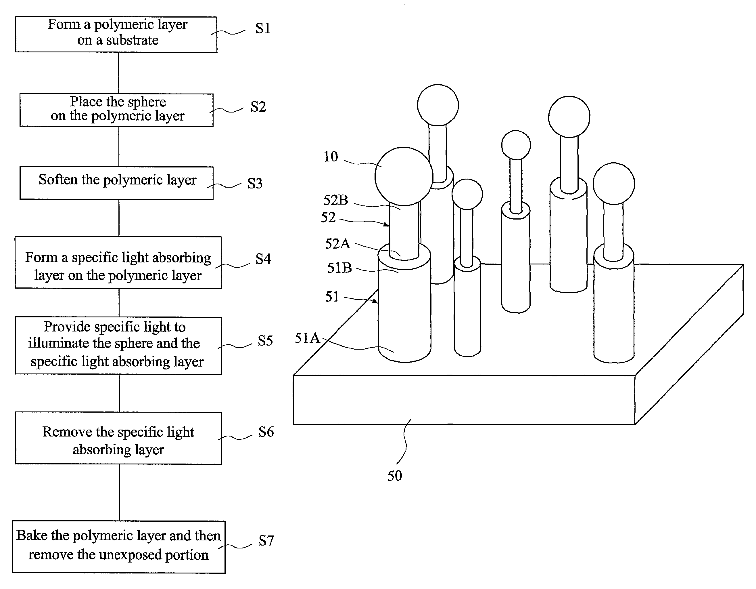
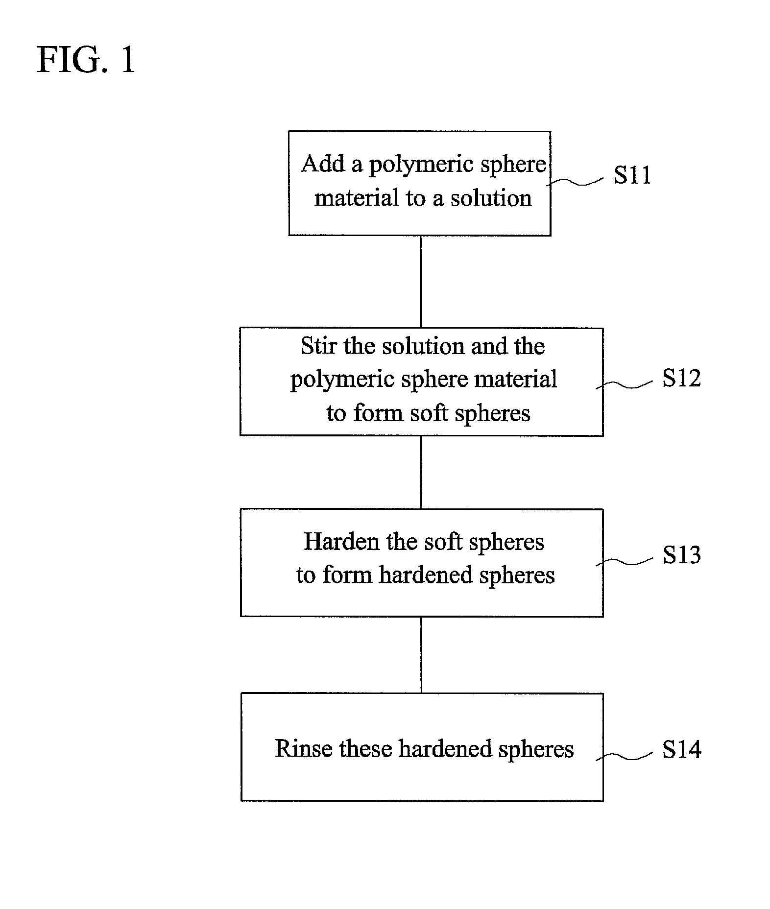
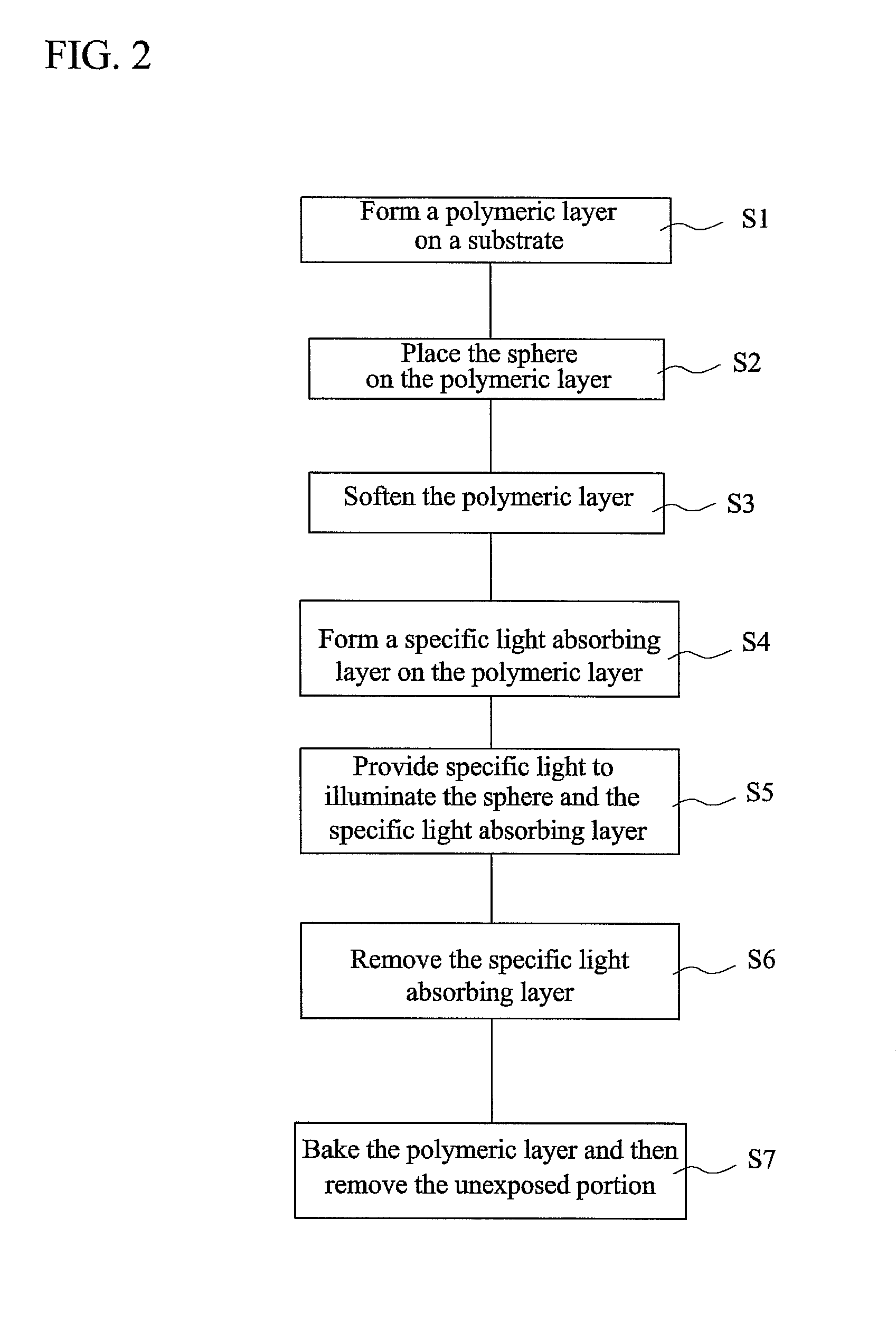
[0023]FIG. 1 is a flow chart showing a method of manufacturing a sphere for a self-aligned stylus with high sphericity according to a preferred embodiment of the invention. The sphere is a micro-sphere with high sphericity and may be manufactured according to various methods. In the following example, one method will be illustrated.

[0024]As shown in FIG. 1, the sphere may be formed according to the following steps. First, in step S11, a polymeric sphere material (e.g., an SU-8 material) is added to a solution, such as a sodium dodecylbenzenesulfonate (NaDBS) solution. In this step, the density of the NaDBS solution has to be adjusted to be the same as that of the SU-8 polymeric material so that the effect of gravity on the SU-8 polymeric material can be eliminated during the manufactu...


PUM


Abstract

A method of manufacturing a self-aligned stylus with high sphericity includes the steps of: forming a polymeric layer on a substrate; placing a sphere on the polymeric layer; softening the polymeric layer to make a portion of the sphere sink into the polymeric layer; forming a specific light absorbing layer on the polymeric layer; illuminating the sphere and the specific light absorbing layer with specific light such that the specific light is focused by the sphere to expose the polymeric layer to form an exposed portion and an unexposed portion; removing the specific light absorbing layer; and baking the polymeric layer and then removing the unexposed portion. A self-aligned stylus with high sphericity is also disclosed.

Description

[0001]This application claims priority of No. 096140519 filed in Taiwan R.O.C. on Oct. 29, 2007 under 35 USC 119, the entire content of which is hereby incorporated by reference.BACKGROUND OF THE INVENTION[0002]1. Field of Invention[0003]The invention relates to a stylus and a method of manufacturing the same, and more particularly to a self-aligned stylus with high sphericity and a method of manufacturing the same.[0004]2. Related Art[0005]The trend towards miniaturization and modularization in manufacturing has led to a requirement for a coordinate measuring machine (CMM) capable of measuring tiny features on small components. Surface profilers, micro coordinate measurement machines (μCMMS), and scanning probe microscopes (SPMs) have been developed to measure three dimensional coordinates of structures from nanometer to micrometer scales. As for the high-precision micro-metrology, in order to measure three-dimensional features, such as deep trenches, sidewalls and nozzles, having ...

Claims


Application Information

Patent Timeline
Patent Type & Authority Patents(United States)
IPC IPC(8): G01B5/008
CPCG01B1/00G01B5/012
Inventor SHIH, WEN-PINTSAI, YAO-CHUANCHANG, DUO-RUTSAO, LI-CHIWU, MING-DAOSHIH, PO-JEN
Owner NAT TAIWAN UNIV
Why Eureka
Try Eureka