Cu Core Ball, Solder Joint, Solder Paste and Formed Solder

a technology of solder paste and solder core, which is applied in the direction of metal-working apparatus, solid-state devices, metallic material coating processes, etc., can solve the problems of poor adhesion between a surface of the cu ball and a metal layer, cu ball is not suitable for being coated by the metal layer, and the self-alignment property of the cu ball to deteriorate, etc., to achieve suppressed discoloration, low hardness, and high sphericity

Active Publication Date: 2019-12-12
SENJU METAL IND CO LTD
View PDF4 Cites 5 Cited by
  • Summary
  • Abstract
  • Description
  • Claims
  • Application Information

AI Technical Summary

Benefits of technology

[0014]According to the present invention, the Cu ball having a high sphericity and a low hardness is realized and the discoloration thereof is suppressed. It is capable of realize a high sphericity of the Cu core ball in which a metal layer covers the Cu ball by realizing the high sphericity of the Cu ball. It is possible to maintain a self-alignment property when installing the Cu core balls on the electric electrodes and to prevent the Cu core balls from varying in the heights thereof. In addition, it is capable of improving impact resistance to dropping in the Cu core ball in which a metal layer covers the Cu ball by realizing the low hardness of the Cu ball. Further, since the discoloration of the Cu ball is suppressed, it is possible to prevent the Cu ball from being adversely affected by any sulfide or sulfur oxide, thereby being suitable for being coated by the metal layer and improving a wettability thereof.

Problems solved by technology

The discoloration of the Cu ball may cause the wettability thereof to deteriorate and the deterioration of the wettability may lead to a generation of a condition that is not wetted or cause a self-alignment property thereof to deteriorate.
Thus, since, in the Cu ball which is easy to discolor, for example, an adhesion between a surface of the Cu ball and a metal layer becomes worse and the metal layer has a high oxidizable surface or a surface with high reactivity, such a Cu ball is not suitable for being coated by the metal layer.

Method used


Image

  • Cu Core Ball, Solder Joint, Solder Paste and Formed Solder
  • Cu Core Ball, Solder Joint, Solder Paste and Formed Solder
  • Cu Core Ball, Solder Joint, Solder Paste and Formed Solder

Examples


first embodiment

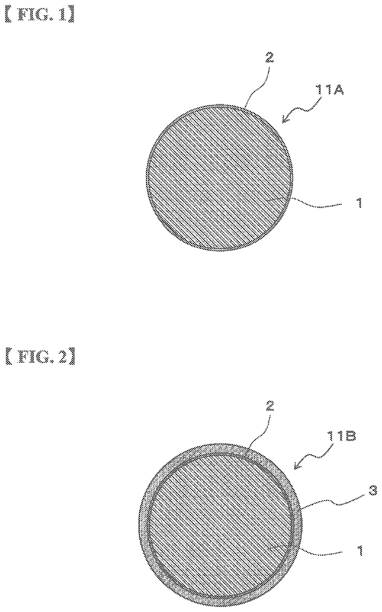
[0022]FIG. 1 shows a configuration example of a Cu core ball 11A according to the prevent invention. As shown in FIG. 1, the Cu core ball 11A contains a Cu ball 1 and one or more metal layer 2 for covering a surface of the Cu ball 1, each layer including one or more element selected from the group of Ni, Co, Fe and Pd.

second embodiment

[0023]FIG. 2 shows a configuration example of a Cu core ball 11B according to the prevent invention. As shown in FIG. 2, the Cu core ball 11B contains a Cu ball 1, one or more metal layer 2 that covers a surface of the Cu ball 1, each layer including one or more element selected from the group of Ni, Co, Fe and Pd and a solder layer 3 that covers a surface of the metal layer 2.

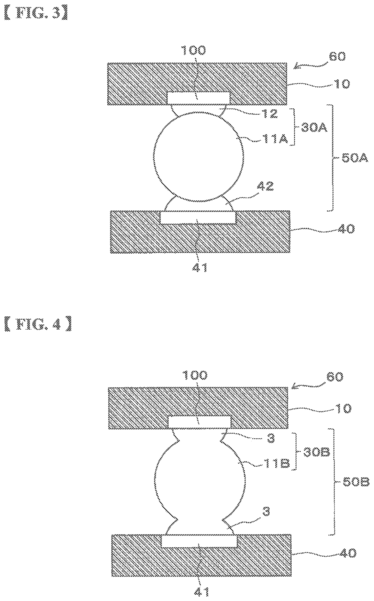
[0024]FIG. 3 shows a configuration example of an electronic component 60 in which a semiconductor chip 10 is mounted on a printed circuit board 40 using the Cu core ball 11A according to the first embodiment of the prevent invention. As shown in FIG. 3, the Cu core ball 11A is installed on an electrode 100 of the semiconductor chip 10 via solder paste 12. In this example, a structure in which the Cu core ball 11A is installed on the electrode 100 of the semiconductor chip 10 is called a solder bump 30A. Solder paste 42 is printed on an electrode 41 of the printed circuit board 40. The solder bump 30A of the se...


PUM

PropertyMeasurementUnit
sphericityaaaaaaaaaa
diameteraaaaaaaaaa
sphericityaaaaaaaaaa

Abstract

The Cu core ball contains a Cu ball and one or more metal layer for covering a surface of the Cu ball, each layer including one or more element selected from Ni, Co, Fe and Pd. The Cu ball contains at least one element selected from Fe, Ag, and Ni in a total amount of 5.0 or more to 50.0 ppm by mass or lower, S in an amount of 0 ppm by mass or more to 1.0 ppm by mass or lower, P in an amount of 0 ppm by mass or more to less than 3.0 ppm by mass, and remainder of Cu and inevitable impurities. The Cu ball contains purity which is 99.995% by mass or higher and 99.9995% or lower, sphericity which is 0.95 or higher and a diameter of 1 μm or more to 1000 μm or lower.

Description

CROSS REFERENCE TO RELATED APPLICATION[0001]This application claims priority to Japanese Patent Application JP 2018-111872 filed Jun. 12, 2018, the disclosure of which is hereby incorporated by reference in its entirety.BACKGROUND OF THE INVENTIONField of the Invention[0002]The present invention relates to a Cu core ball in which a metal layer(s) cover(s) a Cu ball, a solder joint using the Cu core ball, solder paste using the same and formed solder using the same.Description of Related Art[0003]Recently, along development of compact information equipment, electronic components to be mounted have been downsized rapidly. A ball grid alley (hereinafter referred to as “BGA”) having electrodes at its rear surface has been applied to such electronic components in order to cope with a narrowed connection terminal and a reduced mounting area because of the downsizing requirement.[0004]As the electronic components to which the BGA is applied, for example, a semiconductor package is exemplif...

Claims


Application Information

Patent Timeline
Patent Type & Authority Applications(United States)
IPC IPC(8): B23K35/30B23K35/02B22F1/00B22F1/065B22F1/14B22F1/142B22F1/17
CPCB23K35/302B23K35/025B22F1/142B22F1/00B22F1/065B22F1/14B22F1/17H01L2924/15311H01L2924/20105H01L24/13H01L24/16H01L24/11H01L24/81H01L23/49816H01L2224/16227H01L2224/13016H01L2224/13657H01L2224/81815H01L2224/13582H01L2224/13655H01L2224/13611C23C30/00C22C9/00C23C30/005C22C9/06C23C28/02C22C9/02C23C28/00C22C13/00C23C28/021C23C28/023B32B15/01B32B15/04B32B15/043B23K35/262B23K35/0238B23K35/365B23K35/0244B23K35/3033B23K35/3602B23K35/0227B23K35/3046G01N2021/95646G01N21/95684G01N21/951G01N21/25Y10T428/12722Y10T428/1291Y10T428/12229Y10T428/12931Y10T428/12708Y10T428/12944Y10T428/12014Y10T428/12222Y10T428/12937Y10T428/12993Y10T428/12493Y10T428/12104Y10T428/12028Y10T428/12917Y10T428/12903Y10T428/12715Y10T428/29Y10T428/2991Y10T428/12924Y10T428/2495Y10T428/2982Y10T428/26Y10T428/12875
Inventor KAWASAKI, HIROYOSHIKONDOH, SHIGEKISUDO, HIROKITSUCHIYA, MASATOYASHIMA, TAKASHIROPPONGI, TAKAHIROSOMA, DAISUKE
Owner SENJU METAL IND CO LTD
Why Eureka
Try Eureka