Parking device of transmission

a technology of a transmission and a parking device, which is applied in the direction of gearing details, braking systems, transportation and packaging, etc., can solve the problems of troublesome attachment work of the support member to the transmission case, increase in complex structure of the supporting member, so as to reduce the number of parts, improve the attaching work, and achieve the effect of proper operation

Active Publication Date: 2012-08-14
MAZDA MOTOR CORP
View PDF7 Cites 18 Cited by
  • Summary
  • Abstract
  • Description
  • Claims
  • Application Information

AI Technical Summary

Benefits of technology

[0008]An object of the present invention is to provide a parking device of a transmission which can decrease the number of parts, improve the attaching work, obtain the proper operation by maintaining a constant state of the cam portion of the parking rod pressing the parking pole, and hold the support member firmly against the reaction for the superior operation and durability.

Problems solved by technology

However, in case plural bolts are used for the fixing or both the bolts and the positioning pin are used when the support member is supported at the transmission case, the structure of supporting the support member would become complex, the number of parts would increase, and the attaching work of the support member to the transmission case would become troublesome.
Accordingly, the support rigidity of the support member would be improperly insufficient.
Meanwhile, the parts would become improperly large sized in order to solve this problem.

Method used


Image

  • Parking device of transmission
  • Parking device of transmission
  • Parking device of transmission

Examples


Embodiment Construction

[0027]Hereinafter, a preferred embodiment of the present invention will be described referring to the accompanying drawings.

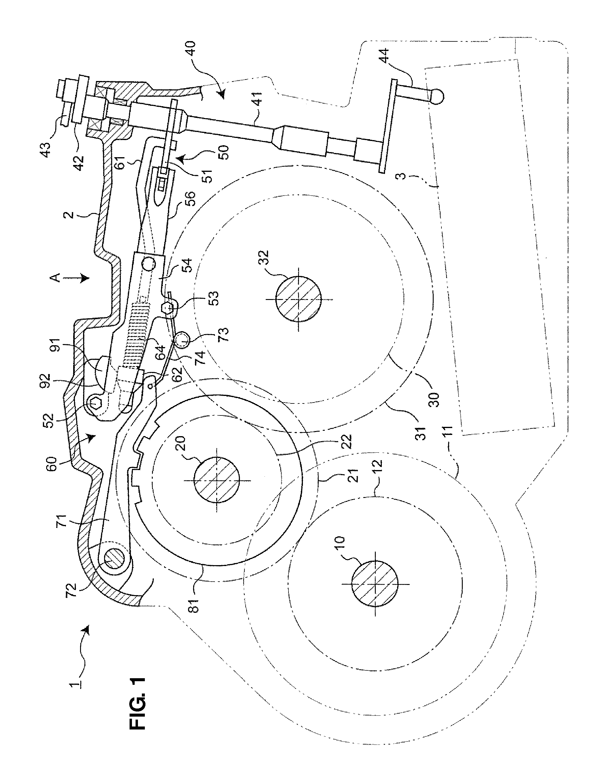
[0028]FIG. 1 shows a schematic sectional structure of a transmission for a front-engine front-drive vehicle. This transmission 1 comprises a primary shaft 10 which is arranged coaxially with an output shaft (not shown) of an engine, a secondary shaft 20 which is arranged rearward and above the secondary shaft 20, and a differential gear 30 having its axis arranged rearward and below the secondary shaft 20.

[0029]The output of the engine is changed in speed through a transmission mechanism 11 on the primary shaft 10 according to the engine operating condition, and then transmitted to a first gear 21 on the secondary shaft 20 from an output gear 12. Then, it is transmitted from a second gear 22 on the secondary shaft 20 to a ring gear 31 of the differential gear 30, and eventually to both vehicle axels 32, 32 (only one is illustrated) via the differential gear 30....


PUM


Abstract

According to an operation of a shift lever to parking range, a cam member at a parking rod comes in between a parking pole and a support member, and the parking pole swings so that a pawl portion of the parking rod can engage with a parking gear. A concave holding portion to hold the support member is formed at a transmission case. The support member comprises a first cylindrical outer face having a first radius R1 which is supported in a concave inner face the concave holding portion to rotate in a specified range and a second cylindrical outer face (cam-contact portion) having a second radius R2 which contacts a cam member. The first radius R1 has a center which is located at the same position as that of the second radius R2. Herein, R2 is shorter than R1.

Description

BACKGROUND OF THE INVENTION[0001]The present invention relates to a parking device of a transmission which may be installed in automotive vehicles.[0002]In general, the transmission for automotive vehicles has the parking device to prevent the vehicle parked on a slope from moving unexpectedly. The parking device comprises a parking gear provided at a rotational member on an output side of the transmission, a parking pole to swing and make its pawl portion lock the parking gear through their engagement, and a parking rod to move together with an operation of a shift lever by a driver and have a cam portion press the parking pole for their engagement according to the operation of the shift lever.[0003]Further, the parking device comprises a support member which is provided beside the cam portion of the parking rod on an opposite side to the parking pole. This support member receives a reaction force which acts on the cam portion of the parking rod which occurs in case of pressing of ...

Claims


Application Information

Patent Timeline
Patent Type & Authority Patents(United States)
IPC IPC(8): B60T1/06
CPCB60T1/005F16H63/3416F16D63/006Y10T74/19637
Inventor HONGAWARA, NARIHITOHATA, TOMOYUKIHONDA, YUICHIIWASAKI, TATSUHIKO
Owner MAZDA MOTOR CORP
Why Eureka
Try Eureka