Micro-scale and meso-scale hydraulic and pneumatic tools, methods for using, and methods for making
a hydraulic and pneumatic tool, micro-scale technology, applied in the direction of piston pumps, rod connections, applications, etc., can solve the problems of destructive separation of masking materials from substrates, and achieve the effect of reducing assembly costs, improving functionality, and reducing fabrication costs
- Summary
- Abstract
- Description
- Claims
- Application Information
AI Technical Summary
Benefits of technology
Problems solved by technology
Method used
Image

Examples
embodiment 1
Hydraulic Scissors
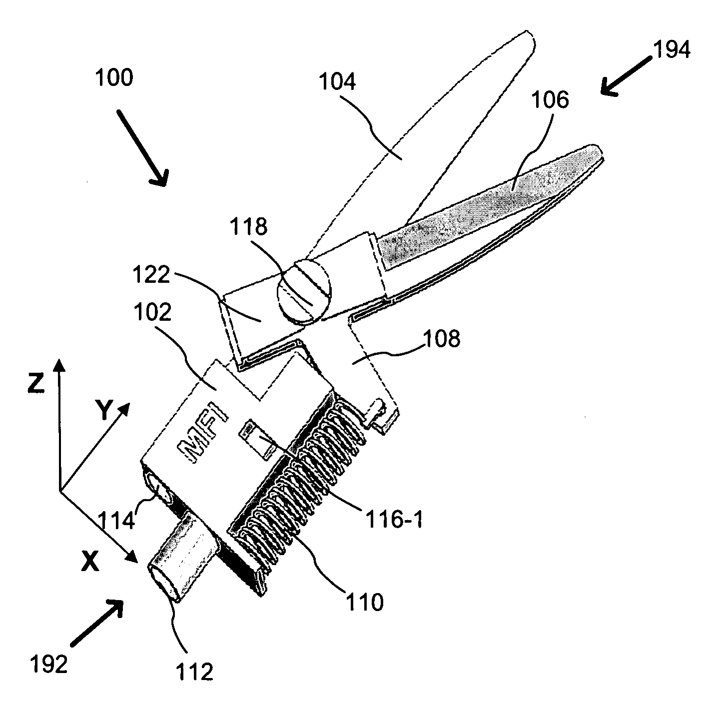
[0129]FIGS. 5A-17 provide various views of a first embodiment of the invention that provides a hydraulic scissors example. When forming the device via multi-layer, multi-material electrochemical fabrication methods it is preferred that the device be fabricated on its so as to minimize the number of layers used in forming it as well as to take advantage of the processes ability to form smooth curves in the planes of layers.
[0130]FIG. 5A provides a top perspective view of the hydraulic scissors 100 of the present embodiment while FIG. 5B provides a bottom perspective view of the scissors. The scissors possess a distal end 194 and a proximal end 192. According to this embodiment the scissor have a fixed blade 104 and a movable blade 106 connected together by a pivot 118 (e.g. a ¼ turn pin or connector as illustrated) that includes a slotted flat head on the upper side and an elongated base on the bottom side. The elongated base is configured to pass through the moving...
embodiment 2
Hydraulic Forceps
[0142]FIGS. 18A-25 provide various views of a second embodiment of the invention that provides hydraulic forceps. When forming the device via multi-layer, multi-material electrochemical fabrication methods it is preferred that the device be fabricated on its so as to minimize the number of layers used in forming it as well as to take advantage of the processes ability to form smooth curves in the planes of layers.
[0143]FIGS. 18A and 18B provide a perspective top view and a perspective and cut top view, respectively, of a micro-forceps device 200 according a second embodiment. FIG. 18C provides a perspective top view from another angle while FIG. 18D provide a perspective bottom view. The forceps of the present embodiment may be used directly in conjunction with a handle or they may be used at the end of a tube, wire or cable inserted into a working location via a catheter or other lumen. The forceps of the present embodiment provide curved arms / jaws 204 and 206 that...
embodiment 3
Hydraulic Rotary Actuator
[0153]FIGS. 26A-26B provide views of a third embodiment of the invention that provides a hydraulic rotary actuator 300 that may be used to operate a variety of useful medical tools. In the present embodiment, a saw blade 306 is attached to the shaft of the actuator. In other embodiments, other tools could be attached. Examples of such tools include drill bits, grinders, polishers, eccentric elements that convert the rotary motion into linear or nearly linear motion, eccentrics that cause oscillatory motion or vibratory motion.
[0154]The principle of operation for the rotary actuator of the present embodiment involves the use of viscous drag across a propeller to induce rotational motion. As fluid flows past the blades of the rotor, the blades pick up momentum from the flowing fluid and begin to rotate
[0155]This device has two main components as seen in FIG. 26A, the “housing”302 and “tool”306. The housing has two ports, either of which may be used as an the i...
PUM
 Abstract
Description
Claims
Application Information
 - R&D Engineer
- R&D Manager
- IP Professional
- Industry Leading Data Capabilities
- Powerful AI technology
- Patent DNA Extraction
Browse by: Latest US Patents, China's latest patents, Technical Efficacy Thesaurus, Application Domain, Technology Topic.
© 2024 PatSnap. All rights reserved.Legal|Privacy policy|Modern Slavery Act Transparency Statement|Sitemap