
Video method for generating free viewpoint video image using divided local regions

a video image and local region technology, applied in the field of video method for generating free viewpoint video image, can solve the problems of increasing the number of cameras, raising the cost, and the inability to obtain the video image located between the video cameras, and achieve the effect of producing a higher degree of realistic sensation

Inactive Publication Date: 2012-08-14
KDDI CORP
View PDF26 Cites 12 Cited by
  • Summary
  • Abstract
  • Description
  • Claims
  • Application Information

AI Technical Summary

Benefits of technology

The present invention provides a method for generating a free viewpoint video image that can be seen from a virtual viewpoint that is not located on the same plane as the camera. The method involves dividing a real zone into local regions, transforming the camera coordinate system within each region to match its distance to the object, and generating a video image within each region using image-based rendering. The video images from each region are then integrated to create the free viewpoint video image. The method allows for a more realistic sensation and allows for the virtual viewpoint to be moved in any direction.

Problems solved by technology

In this case, if cameras are disposed densely around an object in order to cope with an arbitrary viewpoint, the number of the cameras is increased thereby raising cost, which is not achievable in reality.
Thus, although a method of disposing the cameras sparsely around the object is adopted, in this case, a video image located between video cameras is not obtained.
However, when objects are distributed in a wide range in a real zone and parallax due to a difference in depth (depth parallax) is large, if it is intended to correct that depth parallax by the above-mentioned prior art, interpolation processing of ray information becomes complicated, which is not an actual solution.
In other words, if the camera is moved in the vertical direction with respect to the plane, the free viewpoint video image cannot be generated.

Method used


Image

  • Video method for generating free viewpoint video image using divided local regions
  • Video method for generating free viewpoint video image using divided local regions
  • Video method for generating free viewpoint video image using divided local regions

Examples


first embodiment

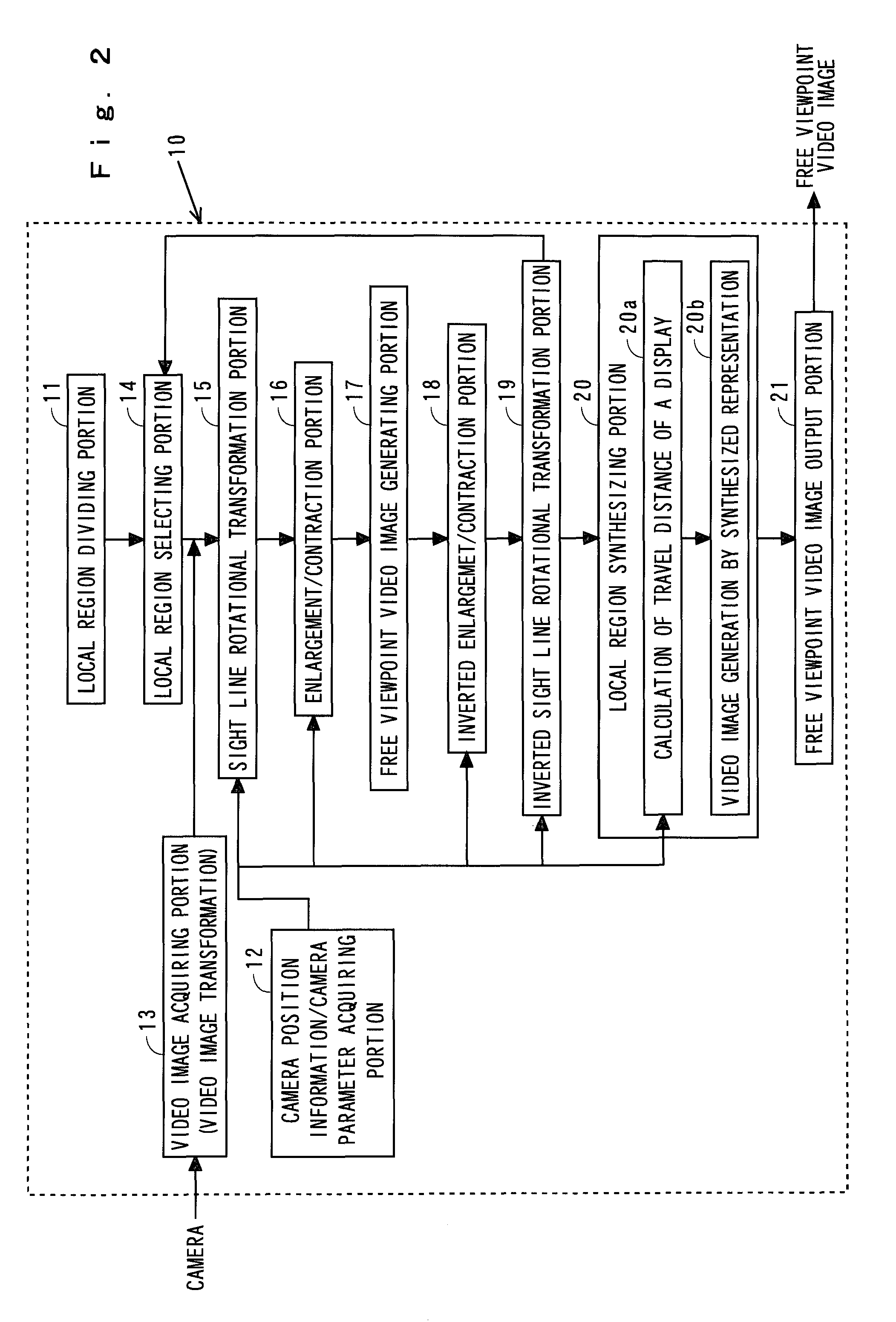
[0032]Next, the structure of a free viewpoint video image generating apparatus 10 of the present invention will be described with reference to a block diagram of FIG. 2.

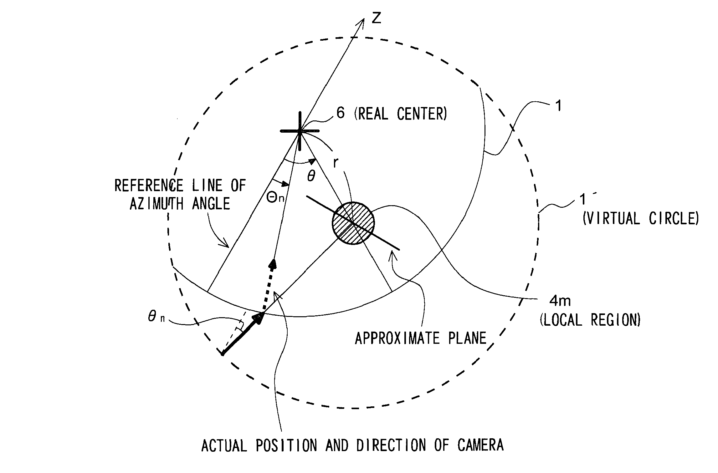
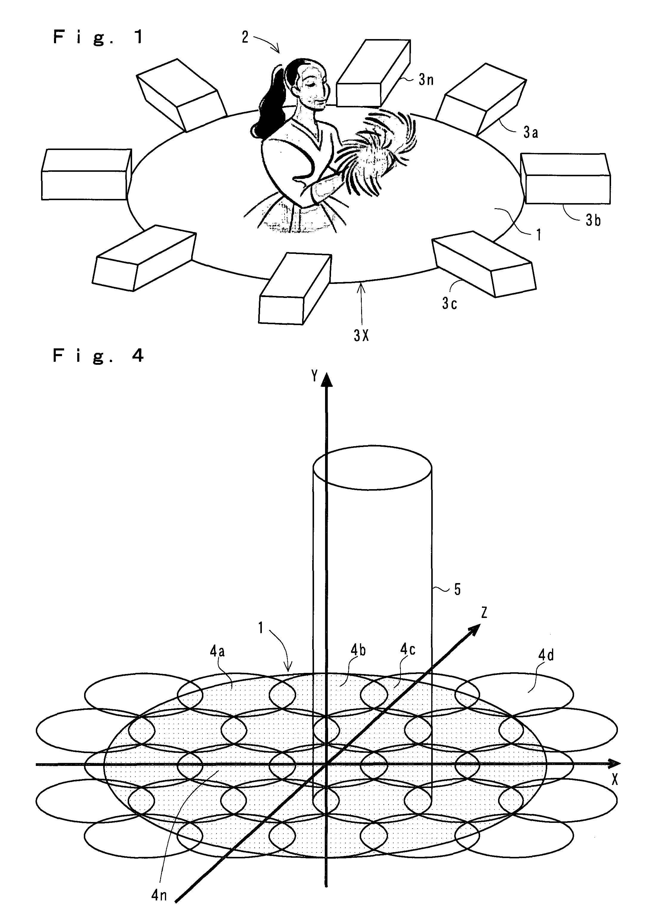
[0033]First, the free viewpoint video image generating apparatus 10 includes a local region dividing portion 11 for dividing a real zone 1 (see FIG. 1) surrounding the object into a plurality of local regions, a camera position information / camera parameter acquiring portion 12 for acquiring position information of the plurality of the cameras 3a, 3b, 3c . . . 3n, virtual viewpoint position information and internal parameters of the camera and a video image acquiring portion 13 for acquiring video image information from the plurality of the cameras 3a, 3b, 3c . . . 3n. In the meantime, the detail of the function of the local region dividing portion 11 will be described with reference to FIG. 4 and FIG. 5 later.

[0034]A local region selecting portion 14 selects one of local regions divided by the local region dividing p...

second embodiment

[0115]The processing of the second embodiment other than described above is the same as the invention mentioned previously (Japanese Patent Application No. 2006-185648) and thus description thereof is omitted.

[0116]FIG. 13 is a diagram showing an example of a result of practical simulation by applying the present invention. (a) is a video image on a horizontal plane of a first stage where a camera is disposed, (b) is a video image when the camera is moved upward by 120 cm and (c) is a video image when the camera is moved downward by 120 cm. If the camera is moved upward from the state of (b), evidently, a forward image is descended largely and the degree of descent of the video image is decreased as it goes deeper. Further, if the camera is moved downward from the state of (c), evidently, the forward image is ascended largely and the ascent of the image is decreased as it goes deeper. This coincides with it that the travel distance Δvi and the reading position Q′ expressed in the eq...


PUM


Abstract

The present invention provides a method of generating a virtual viewpoint video image when the virtual viewpoint position is not located on a plane where a camera is disposed. In an environment in which a plurality of cameras having a horizontal optical axis are disposed in a real zone (for example, on the circumference) which surrounds an object, a video image of an arbitrary viewpoint on the circumference is generated. Further, by synthesizing video images photographed by a camera, a free viewpoint video image is generated from a virtual viewpoint (viewpoint from a high or low position) where no camera is placed. According to a method of achieving this, a travel distance of a display position is calculated by the local region synthesizing portion and this travel distance is reflected to the free viewpoint video image of a local region.

Description

BACKGROUND OF THE INVENTION[0001]1. Field of the Invention[0002]The present invention relates to a method for generating free viewpoint video image using divided local regions and more particularly to a method for generating a free viewpoint video image using images of an object photographed with a plurality of video cameras (hereinafter referred to as just camera) having each horizontal optical axis so as to surround the object.[0003]2. Description of the Related Art[0004]With a progress of video processing technology and video communication technology in recent years, three-dimensional free viewpoint video image has been attracting public attention as a next-generation video content. Then, a technology of generating entire circumference free viewpoint video image using multi-viewpoints photographed by disposing video cameras around an object has been studied and developed.[0005]In this case, if cameras are disposed densely around an object in order to cope with an arbitrary viewpo...

Claims


Application Information

Patent Timeline
Patent Type & Authority Patents(United States)
IPC IPC(8): H04N7/00G06T3/00
CPCG06T15/205
Inventor ISHIKAWA, AKIOSAKAZAWA, SHIGEYUKIKOIKE, ATSUSHI
Owner KDDI CORP
Learn More