Clamping device

a technology of clamping device and belt, which is applied in the direction of fluid pressure sealing joint, flexible elements, applications, etc., can solve the problems of reducing the effectiveness of clamping collar, belt forming an additional and costly step in manufacturing the collar,

Active Publication Date: 2012-08-21
ESTAB CAILLAU SARL
View PDF7 Cites 5 Cited by
  • Summary
  • Abstract
  • Description
  • Claims
  • Application Information

AI Technical Summary

Benefits of technology

[0017]In addition, the tightening wall continues to have a certain amount of freedom of movement (so long as it is not in abutment against the projecting portion), thereby making it possible to guarantee good relative positioning and therefore good bearing between said wall and the elements of the tightening system used.
[0021]In an embodiment, said projecting portion is formed by a tongue cut out from the belt and upstanding towards the outside of said belt. This tongue therefore projects relative to the outside face of the belt. Said tongue is terminated by a free end. In a first example, the free end points towards the tightening wall. In which case, the tightening wall can come into abutment against said free end while the collar is being tightened. In a second example, said free end points towards a side face of the collar, and the tightening wall can come into abutment against a side of the tongue while the collar is being tightened. It should be noted that if the tightening forces applied to the tightening wall are large, a tongue that points as in the second example is preferred because there is less risk of it deforming (in particular, there is no risk of it turning over) under the effect of the tightening forces.
[0024]In another embodiment, the tightening wall carries a tab and said projecting portion defines a recess under it that is designed to receive said tab. This co-operation between the tab and the projecting portion can make it possible to limit the possibilities of the tightening wall moving radially and / or to center the tightening wall relative to the belt.

Problems solved by technology

The facing lugs then tilt towards each other, thereby reducing the effectiveness of the clamping of the collar.
However, welding the tightening walls to the belt constitutes an additional and costly step in manufacturing the collar.

Method used


Image

  • Clamping device
  • Clamping device
  • Clamping device

Examples


Embodiment Construction

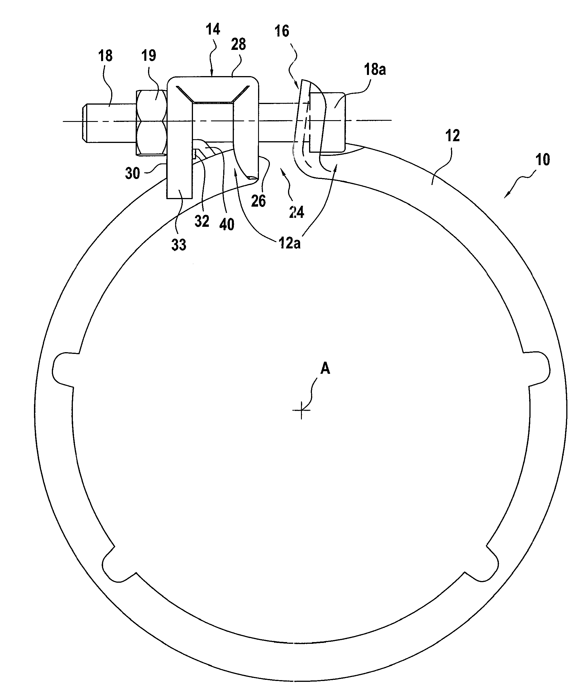
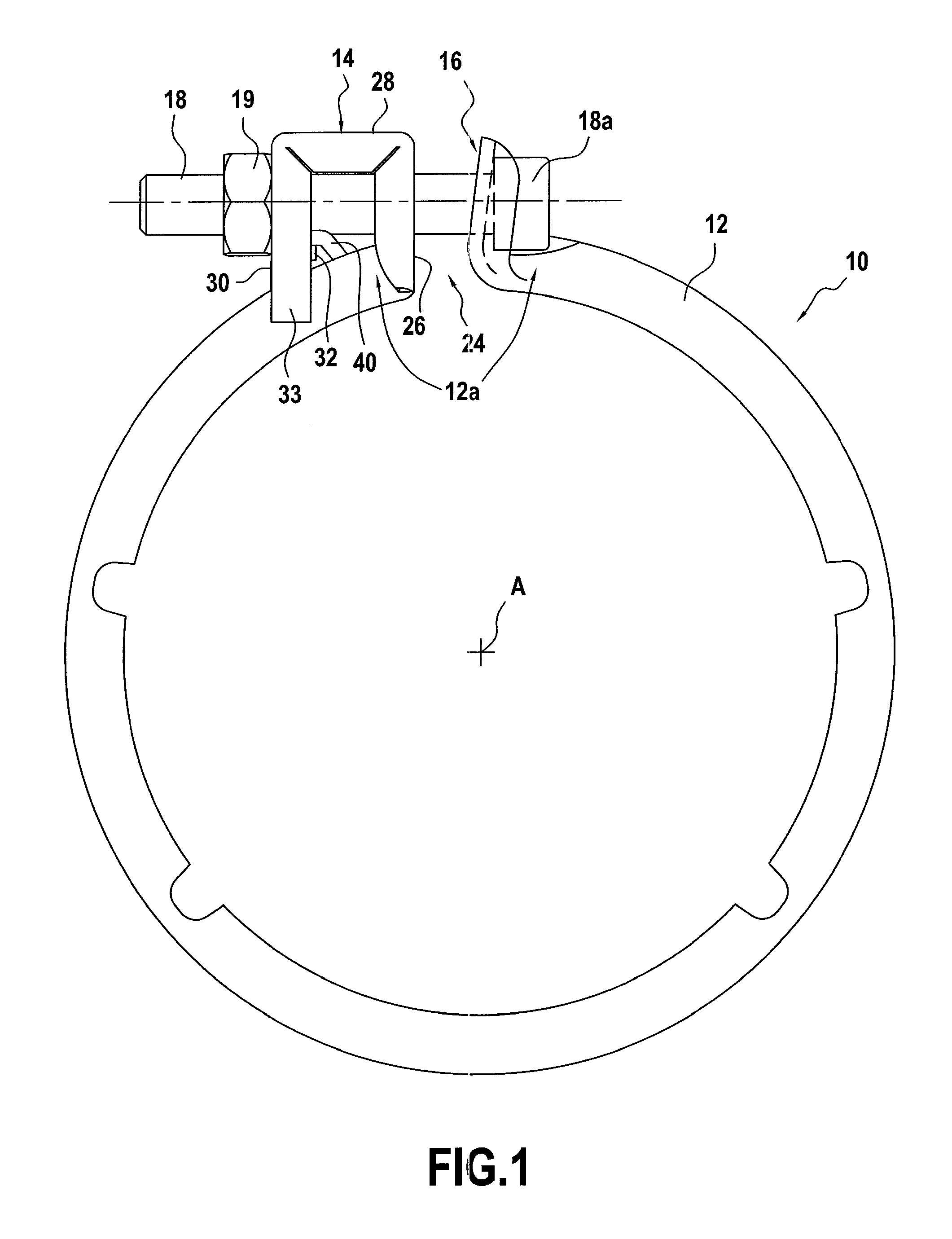
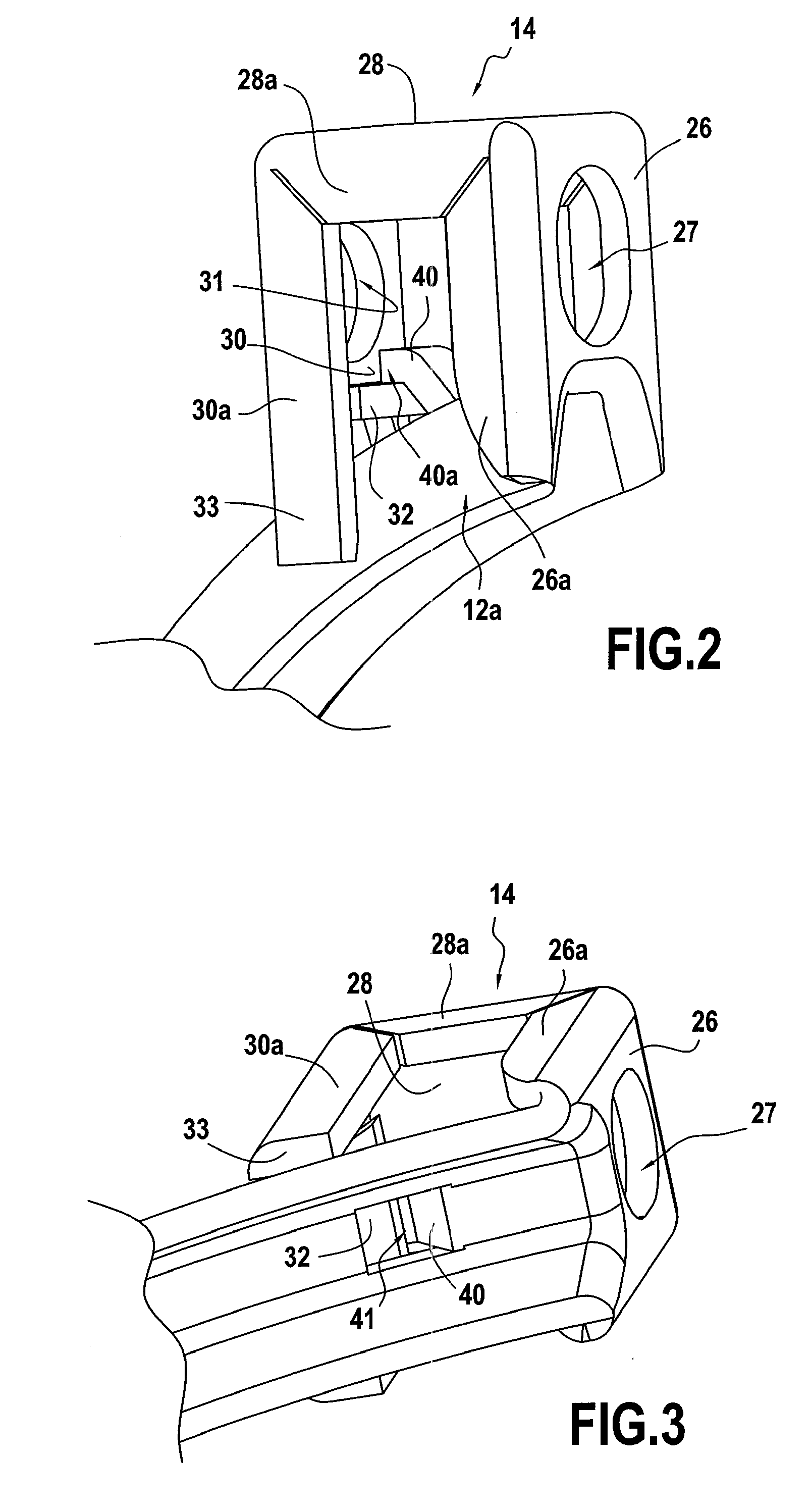
[0038]The clamping device shown in FIGS. 1 to 3 comprises:[0039]a collar 10 with an annular belt 12 of axis A and two lugs 14, 16 integral with the ends 12A of the belt 12 and upstanding relative to said belt, towards the outside thereof, so that the lugs 14, 16 extend substantially radially; and[0040]a tightening system suitable for co-operating with the two lugs 14, 16 so as to bring them closer together in such a manner as to cause the collar to be tightened by reducing the diameter of the belt 12.

[0041]In the example, the collar 10 is made of the same metal strip by deforming said strip by folding and / or die-stamping.

[0042]As can be seen in FIG. 1, the lugs 14, 16 are disposed facing each other and they define a slot 24 between them. The tightening system shown comprises a bolt 18 and a nut 19 co-operating with the threaded shank of the bolt. The nut 19 co-operates with one of the lugs 14, while the head 18a of the bolt 18 co-operates with the other lug 16. Optionally, the shape...


PUM


Abstract

A clamping device comprising: a collar (10) comprising: a belt (12) suitable for being disposed around one or more articles to be clamped, and at least two lugs (14, 16) that are upstanding relative to said belt towards the outside thereof; and a tightening system (18, 19) suitable for co-operating with the two lugs so as to move them closer together; in which device at least one of the two lugs has a connection portion via which it is connected to the belt (26), which connection portion is upstanding relative to said belt, and a tightening wall (30) folded back towards the belt, the tightening system coming into engagement with said tightening wall during tightening of the collar; wherein, on its outside face, the belt (12) has at least one projecting portion (40) situated between the connection portion and the tightening wall, the tightening wall (30) coming into abutment against said projecting portion (40) while the collar is being tightened.

Description

CROSS-REFERENCE TO RELATED APPLICATIONS[0001]This is a 371 national phase application of PCT / FR2008 / 050708 filed 21 Apr. 2008, claiming priority to French Patent Application No. 07 / 54669 filed Apr. 24, 2007, the contents of which are incorporated herein by reference.FIELD OF THE INVENTION[0002]The present invention relates to a clamping device of the type comprising:[0003]a collar comprising a belt suitable for being disposed around one or more articles to be clamped, and at least two lugs that are upstanding relative to said belt towards the outside thereof; and[0004]a tightening system suitable for co-operating with the two lugs so as to move them closer together in such a manner as to cause the collar to be tightened;[0005]in which device at least one of the two lugs has a connection portion via which it is connected to the belt, which connection portion is upstanding relative to said belt, and a tightening wall folded back towards the belt, the tightening system coming into enga...

Claims


Application Information

Patent Timeline
Patent Type & Authority Patents(United States)
IPC IPC(8): F16B2/08F16L33/04F16L33/02
CPCF16L21/065F16L23/08F16L33/04Y10T24/1412Y10T24/1441F16B2/08F16L21/08F16L33/02
Inventor BOUCHIAT, JEROMERIGOLLET, NICOLASMOTTEAU, GERARD
Owner ESTAB CAILLAU SARL
Why Eureka
Try Eureka