
Slurry transport and storage system

a technology of slurry and storage system, applied in the field of slurry, can solve the problems of difficult printing high resolution patterns, open or short circuits, and non-uniform surfaces

Active Publication Date: 2012-08-21
INFINEON TECH AG
View PDF11 Cites 3 Cited by
  • Summary
  • Abstract
  • Description
  • Claims
  • Application Information

AI Technical Summary

Benefits of technology

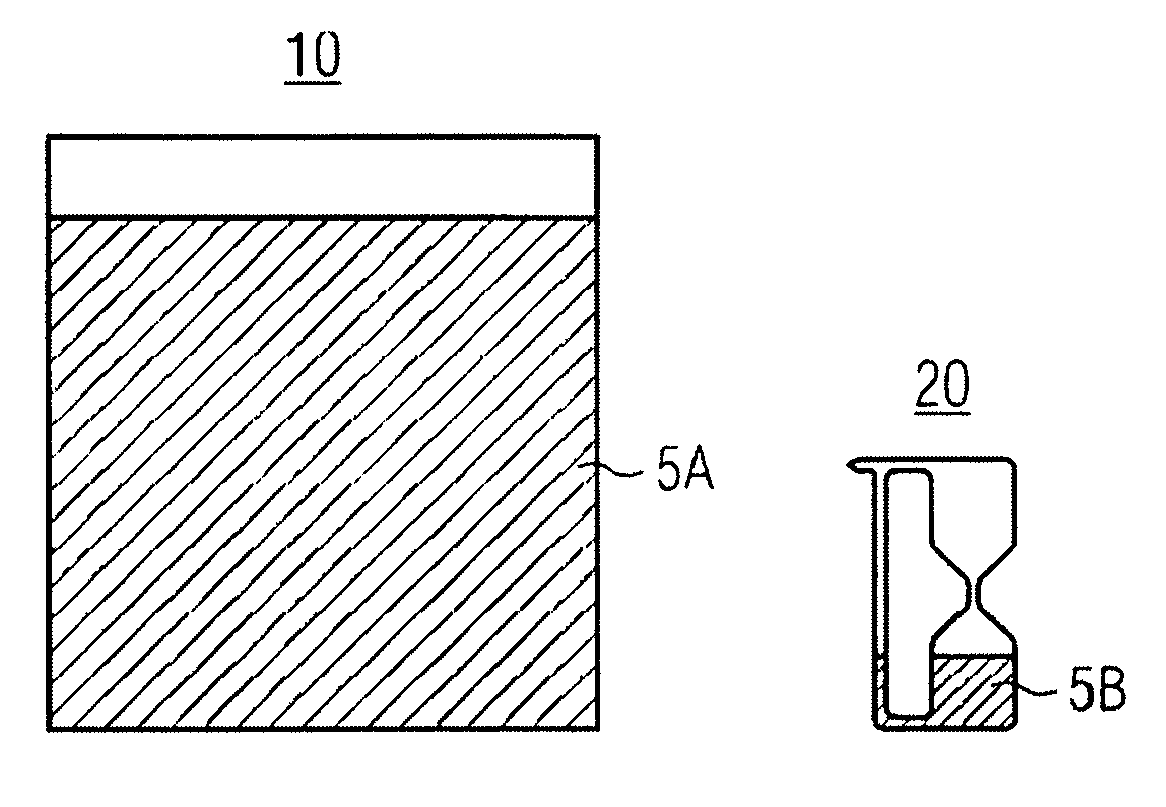
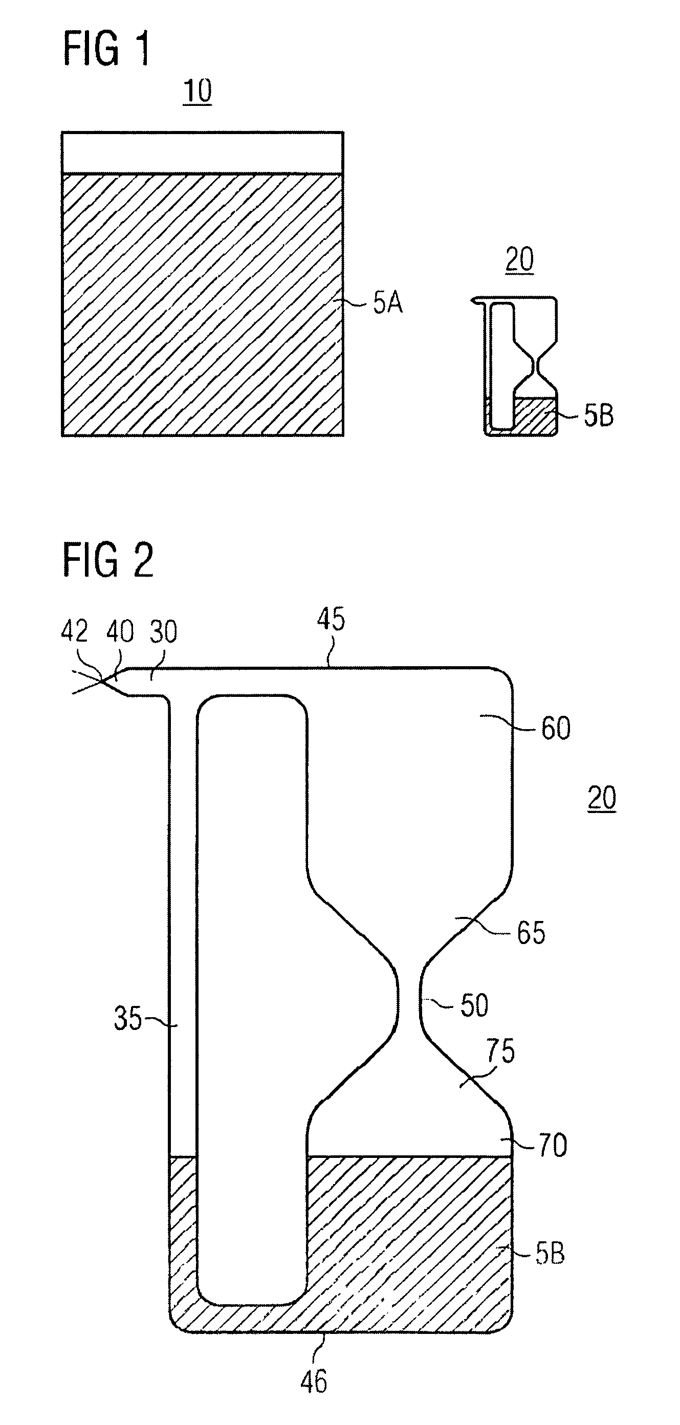
The invention is a system for storing and transporting a slurry. It includes a main container and a test container that are exposed to the same environmental conditions. The test container is designed to determine the viscosity of the slurry. The method involves placing a portion of the slurry in the main container and another portion in the test container, and then determining the viscosity of the slurry in the test container. This allows for the determination of the condition of the slurry during storage or transport.

Problems solved by technology

For instance, metallization layers that provide interconnections between various devices may result in nonuniform surfaces.
The surface nonuniformities may interfere with the optical resolution of subsequent photolithographic steps, leading to difficulty with printing high resolution patterns.
The surface nonuniformities may also interfere with step coverage of subsequently deposited metal layers and possibly cause open or short circuits.
(a) The slurry may dry or inorganic particles in the slurry may flocculate or precipitate during the transport or storage. As a result the concentration and purity of the slurry or the particle size of the inorganic particles in the slurry may differ from those immediately after the preparation, and the desired polishing characteristics may not be obtained. If the slurry has changed its desired polishing characteristic and is used in the planarization process, this can cause to insufficient planarization results. Nonuniform surfaces on the wafer may lead to faults in the circuitry in one of the following process steps. As a result the scrap rate will increase. Very high costs will arise to semiconductor manufacturers by using such altered slurry.
(b) The desired polishing characteristics depend on the type, etc. of the semiconductor devices, etc. to be polished. For this reason, it is necessary to determine the composition, concentration, purity, pH, etc. of the slurry according to the object to be polished. However, it takes the slurry manufacturers very high cost to manufacture the slurry to the composition, concentration, purity, pH, etc. specified by the manufacturers who manufacture and polish semiconductor devices in their orders and supply the same to the manufacturers who manufacture and polish semiconductor devices on the other hand, a method of supplying the slurry prepared to the specified polishing characteristics (compositions, concentrations, purities, pHs, etc.) to the manufacturers who manufacture and polish semiconductor devices for their stock has a problem that the storage period may be longer and the above-described problem (a) may occur.
(c) The slurry which is low in stability is subject to quality deterioration during the storage or transport. Therefore, even if the polishing characteristics of the slurry has high polishing performance immediately after the manufacture, the quality of the slurry may deteriorate during the storage or transport, the polishing performance of the slurry may also deteriorate, and as a result, the slurry may no longer applicable to any industrial uses.

Method used


Image

  • Slurry transport and storage system
  • Slurry transport and storage system
  • Slurry transport and storage system

Examples


Embodiment Construction

[0020]This invention provides a slurry transport and storage system, and more particularly a slurry transport and storage system comprising a main container and a test container, wherein the test container is designed to be able to determine the viscosity of the slurry.

[0021]Main containers are employed to either store a slurry at a fixed location or to transport the slurry from one point to another. A slurry may be transported from one point to another by any means, including but not limited to truck, rail or air. After a slurry is transported to its destination, the slurry may be stored for an indefinite period of time within the main container. Alternatively, at least a portion of the slurry may be transferred from the main container to a slurry distribution system or to another separate storage tank.

[0022]The characteristics of slurries may change over time, with or without changes in the external environmental conditions. Desired characteristics (such as composition, concentrat...


PUM

PropertyMeasurementUnit
diameteraaaaaaaaaa
diameteraaaaaaaaaa
diameteraaaaaaaaaa

Abstract

An embodiment of the present invention is a transport and storage system for a slurry comprising: a main container; and a test container, the main container and the test container being exposed to the same environmental conditions, the main container and the test container containing a slurry from the same batch, wherein the test container is designed to determine the viscosity of the slurry.

Description

FIELD OF THE INVENTION[0001]The present invention relates to slurrys, and, in particular, to slurry transport and storage systems.BACKGROUND OF THE INVENTION[0002]In the manufacture of integrated circuits, planarization of semiconductor wafers is becoming increasingly important as the number of layers used to form integrated circuits increases. For instance, metallization layers that provide interconnections between various devices may result in nonuniform surfaces. The surface nonuniformities may interfere with the optical resolution of subsequent photolithographic steps, leading to difficulty with printing high resolution patterns. The surface nonuniformities may also interfere with step coverage of subsequently deposited metal layers and possibly cause open or short circuits.[0003]Various techniques have been developed to planarize the top surface of a semiconductor wafer.[0004]One of these techniques involves polishing the wafer using polishing slurry that includes abrasive part...

Claims


Application Information

Patent Timeline
Patent Type & Authority Patents(United States)
IPC IPC(8): G01N11/04
CPCG01N11/06
Inventor GEYER, STEFAN
Owner INFINEON TECH AG
Learn More