Slurry-transporting facility and slurry transportation control method

a technology of slurry transportation and control method, which is applied in the direction of machines/engines, water supply installation, and positive displacement liquid engines, etc., can solve the problems of affecting operations, reducing operation efficiency, and slurry backflow, so as to prevent backflow of slurry and perform efficient operations.

Active Publication Date: 2015-11-26
SUMITOMO METAL MINING CO LTD
View PDF4 Cites 3 Cited by
  • Summary
  • Abstract
  • Description
  • Claims
  • Application Information

AI Technical Summary

Benefits of technology

[0027]The present invention enables slurry to be stably transported to a reservoir tank as a transport destination with preventing backflow of the slurry, and can prevent occurrence of a stop of slurry supply to the transport destination even at the time of switchover between pump-equipment circuits for use, and thus makes it possible to perform efficient operations.

Problems solved by technology

In the conventional slurry-transporting facility, if the foregoing switchover control between the pump-equipment circuits, particularly, the pressure condition for the pressure gauge 109 and the pressure gauge 110 which is to be determined in Step S3 is not kept, contents flow backward from the reservoir tank and the pressure in the reservoir tank is decreased, and, as a result, operations are adversely affected.
In this case, downstream steps are also affected, and therefore, it takes at least a few hours or half a day to regain an original normal state, and accordingly, operation efficiency considerably decreases.
However, this technique is to properly operate a high-pressure pump provided at some position in one circuit, and Patent Document 2 does not disclose a technique which makes it possible that, at the time of switchover between two high-pressure-pump-equipment circuits provided to be switched over for maintenance inspections and the like, a continuous operation (slurry supply) is performed with preventing the occurrence of a state in which the feeding is stopped.
Furthermore, the slurry to be subject to the transport is wastewater sludge, human waste, purifying-tank sludge, crushed resin, and the like, and accordingly the technique does not offer high versatility for, for example, slurries which have different properties, such as viscosity, temperature, and pH (for example, the foregoing ore slurry of nickel oxide ore), and is not effectively applied thereto.

Method used


Image

  • Slurry-transporting facility and slurry transportation control method
  • Slurry-transporting facility and slurry transportation control method
  • Slurry-transporting facility and slurry transportation control method

Examples


first embodiment

3-1. First Embodiment

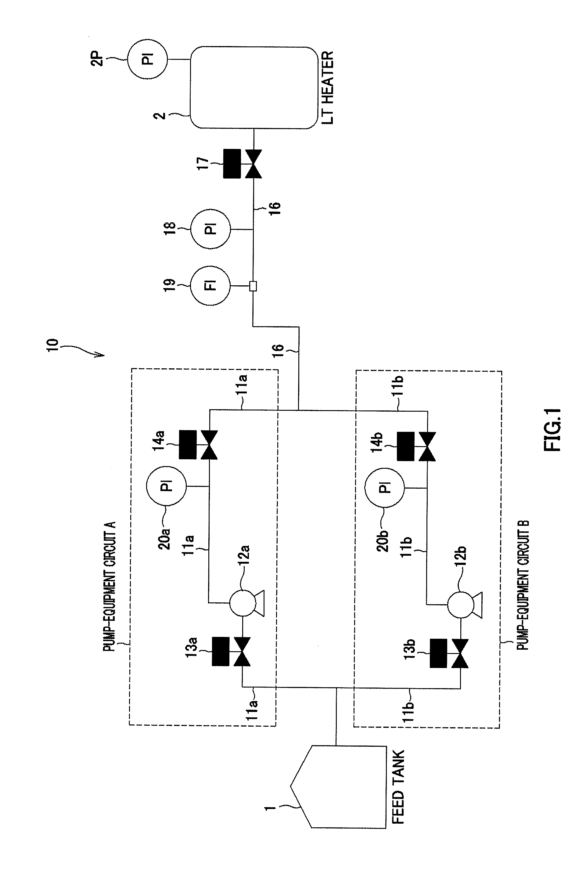
[0091]As a first embodiment, an ore slurry transportation control method using the slurry-transporting facility 10 whose configuration example is illustrated in FIG. 1 will be described. As mentioned above, the slurry-transporting facility 10 is equipped with two pump-equipment circuits (pump-equipment circuit A, pump-equipment circuit B), and is configured to use the two pump-equipment, circuits by suitable switchover between the circuits and transport ore slurry supplied from the feed tank 1 to the LT heater 2 (liquid-transportation at high pressure).

[0092]Here, in the slurry-transporting facility 10, it is important that, with preventing ore slurry to be transported from flowing backward in a flow path, the slurry is surely transported to the LT heater 2 as a transport destination. Ore slurry to be transported has undergone processing under high temperature, high pressure, and the like, and therefore, if the slurry flows backward during the transportation, a ...

modified example

[0111]As a modified example of a switchover process between a plurality of the pump-equipment circuits, the transportation of ore slurry may be controlled in accordance with an operation flow illustrated in FIG. 5. It should be noted that, also in the flow of in FIG. 5, there is shown an example of switchover from the use of the pump-equipment circuit A in an operating state to the use of the pump-equipment circuit B in a waiting state (pump-equipment circuit A→pump-equipment circuit B).

[0112]First, as Step S31, the first valve 13b in a closed state in the pump-equipment circuit B in a waiting state is opened.

[0113]Subsequently, as Step S32, the transport pump 12b in a shutdown state in the pump-equipment circuit B is made into an operating state to start operating.

[0114]Next, in Step S33, a pressure value detected by the pressure gauge 20b configured to detect a pressure in the pipe arrangement 11b to which ore slurry is transported at high pressure by the transport pump 12b having...

second embodiment

3-2. Second Embodiment

In the Case of Pump-Equipment Circuits Each Having not Less than Two Contiguous High-Pressure Pumps

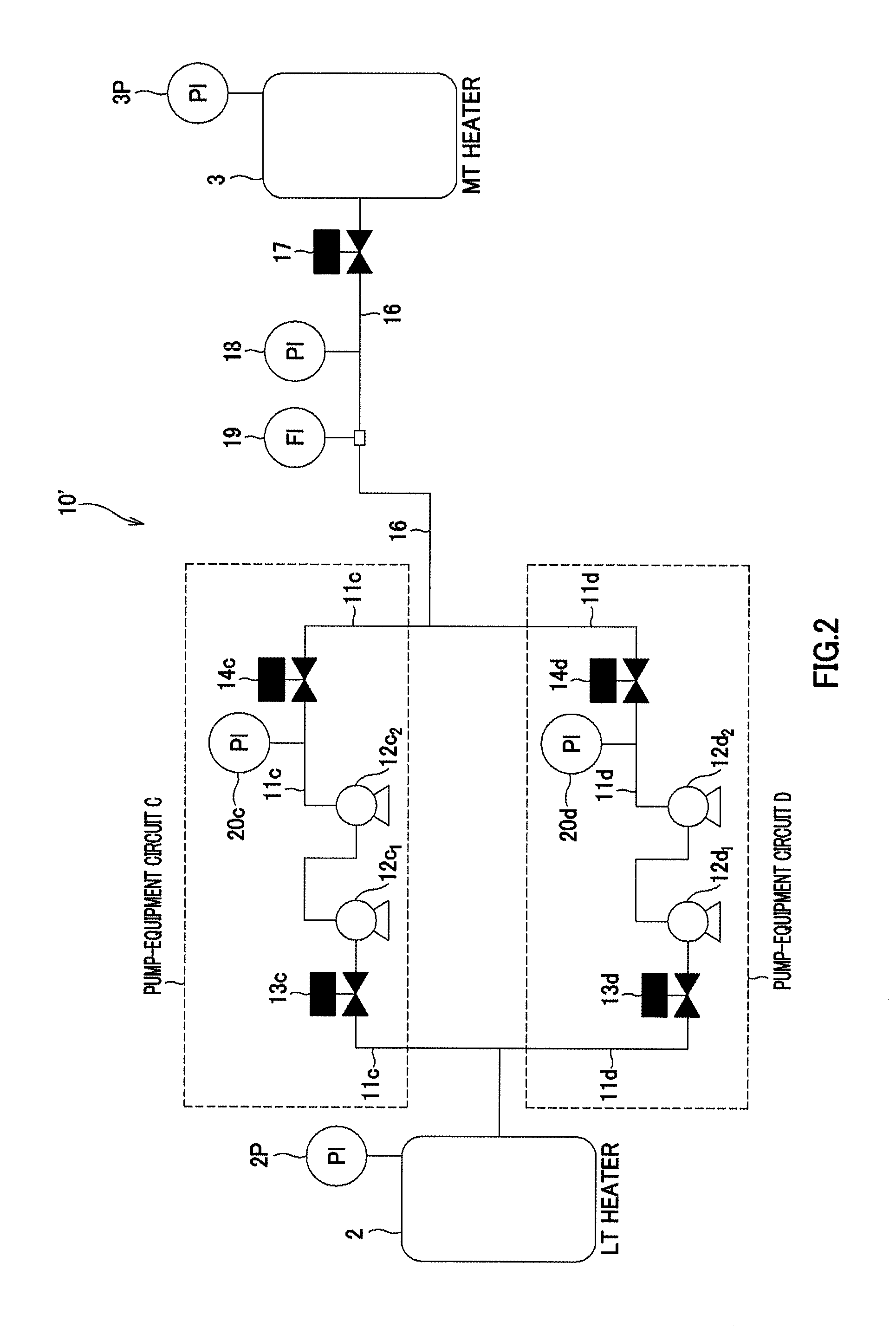
[0122]Next, as a second embodiment, an ore slurry transportation control method using the slurry-transporting facility 10′ whose configuration example is illustrated in FIG. 2 will be described. As mentioned above, the slurry-transporting facility 10′ is equipped with two pump-equipment circuits (pump-equipment circuit C, pump-equipment circuit D), and each of the pump-equipment circuits is equipped with two contiguous transport pumps. Also this slurry-transporting facility 10′ uses the two pump-equipment circuits by suitable switchover between the circuits and transports ore slurry supplied from the LT heater 2 to the MT heater 3 (liquid-transportation at high pressure).

[0123]

[0124]First, an operation at the time of start of ore slurry transportation by the slurry-transporting facility 10′, in other words, a startup operation at a first starting or after shutdown...


PUM

PropertyMeasurementUnit
temperatureaaaaaaaaaa

Abstract

A slurry-transporting facility equipped with a plurality of pump-equipment circuits, whereby a stop of slurry supply to a transport destination at the time of switchover between the pump-equipment circuits for use is prevented to make an efficient operation possible. The slurry-transporting facility includes: pipe arrangements which branch out from a feed tank into the plurality of circuits; a transport pump provided in each of the pipe arrangement; a first valve provided upstream from the transport pump; a second valve provided downstream from the transport pump; and a uniting pipe arrangement formed by joining of the pipe arrangements at a predetermined position and connected to a LT heater. The uniting pipe arrangement is provided with a third valve configured to control the transportation of ore slurry to the LT heater and a pressure gauge configured to measure a pressure in the uniting pipe arrangement.

Description

FIELD OF THE INVENTION[0001]The present invention relates to a slurry-transporting facility and a slurry transportation control method. More specifically, the present invention relates to a slurry-transporting facility which is equipped with a plurality of pump-equipment circuits and configured to use one of the pump-equipment circuits with switching between the circuits and transport slurry to a reservoir tank as a transport destination, and relates to a slurry transportation control method which uses the slurry-transporting facility. The present application claims priority based on Japanese Patent Application No. 2013-002815 filed in Japan on Jan. 10, 2013. The total contents of the patent application are to be incorporated by reference into the present application.BACKGROUND ART[0002]In recent years, high pressure acid leach which uses sulfuric acid has been attracting attention as a hydrometallurgical process which is configured to recover nickel and cobalt from a nickel oxide o...

Claims


Application Information

Patent Timeline
Patent Type & Authority Applications(United States)
IPC IPC(8): F17D3/01F17D1/14
CPCF17D3/01Y10T137/85978Y10T137/0379F17D1/14C22B23/00F04B15/02F04B49/08Y10T137/86163Y10T137/0352Y10T137/87507Y10T137/87314Y10T137/776F04B41/06F17D1/088C22B23/043B01J3/02
Inventor NAKAI, OSAMUMATSUBARA, SATOSHIMITSUI, HIROYUKITACHI, KENJIOKU, MASAYUKI
Owner SUMITOMO METAL MINING CO LTD
Why Eureka
Try Eureka