Cover for electronic device

Active Publication Date: 2012-08-21
SOCLE TECH
View PDF13 Cites 195 Cited by
  • Summary
  • Abstract
  • Description
  • Claims
  • Application Information

AI Technical Summary

Problems solved by technology

However, because only one coil is provided, orientation of the electronic device during charging

Method used


Image

  • Cover for electronic device
  • Cover for electronic device
  • Cover for electronic device

Examples


Embodiment Construction

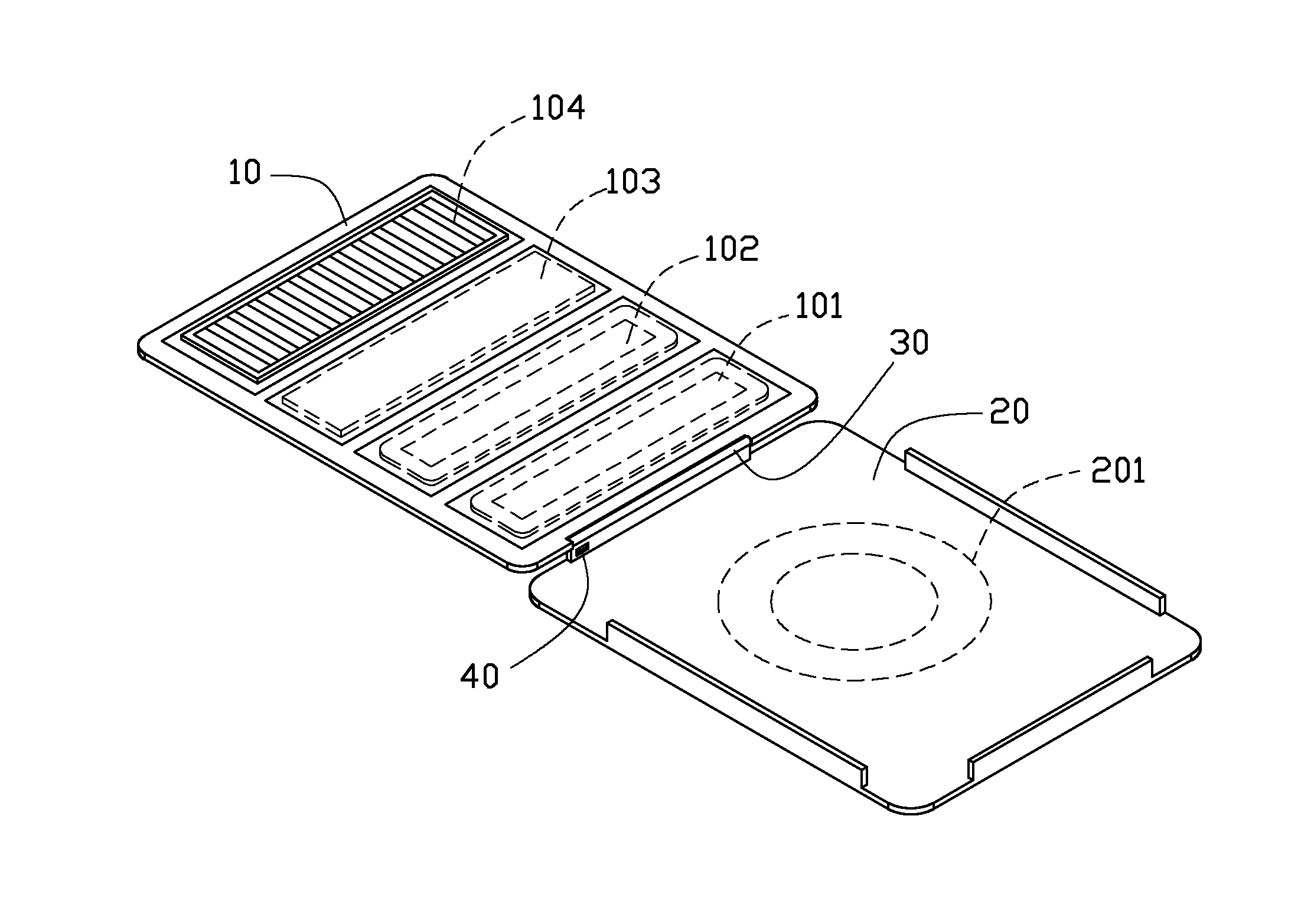
[0010]Referring to FIG. 1, a cover 1 includes a top cover 10 and a bottom cover 20 connected by a hinge 30. The cover 1 further includes an interface 40 for connecting to an electronic device (not shown). A first induction coil 201 is embedded in the bottom cover 20 and is electrically connected to the interface 40.

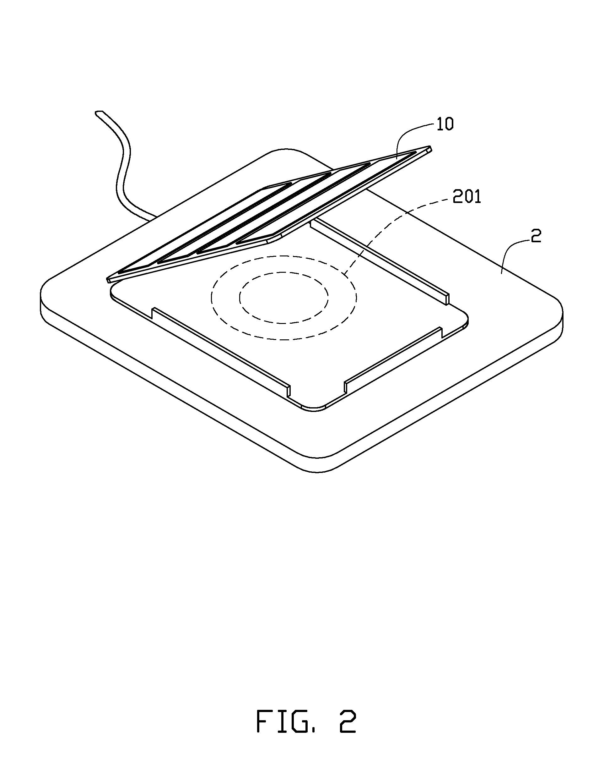
[0011]As shown in FIG. 2, the bottom cover 20 is placed onto a charging base 2 having a primary induction coil (not shown) to charge the electronic device.

[0012]The top cover 10 is substantially sheet-shaped and transversely divided into four parts. Every adjacent two parts can be folded relative to each other a certain degree such that the top cover 10 is folded to support the electronic device at a certain degree. The four parts respectively include imbedded therein a second induction coil 101, a third induction coil 102, a battery 103, and a solar panel 104. The second induction coil 101 and the third induction coil 102 are both connected to the interface 40 and the ba...


PUM


Abstract

The cover includes an interface, a bottom cover and a top cover. The interface is for connecting components embedded in the cover with the electronic device. The bottom cover and the top cover are connected by a hinge and the top cover is divided into at least three parts. Every adjacent two foldable parts can be folded relative to each other to a certain degree such that the top cover is folded to support the electronic device at a certain degree The at least three parts of the top cover includes at least one induction coil which is placed in one of the at least three parts. The top cover is folded to support the electronic device at a certain degree while the induction coil is used to charge for the electronic device.

Description

BACKGROUND[0001]1. Technical Field[0002]The present disclosure relates to electronic device covers, and particularly to a cover with a charging function.[0003]2. Description of Related Art[0004]Currently, some electronic device covers include an induction coil that must be placed onto a charging base to charge the electronic device. However, because only one coil is provided, orientation of the electronic device during charging is limited making it difficult for users to continue using the device while it is being charged.BRIEF DESCRIPTION OF THE DRAWINGS[0005]The components of the drawings are not necessarily drawn to scale, the emphasis instead being placed upon clearly illustrating the principles of the present disclosure. Moreover, in the drawings, like reference numerals designate corresponding parts throughout several views.[0006]FIG. 1 is an isometric view of a cover of an electronic device in accordance with an exemplary embodiment.[0007]FIG. 2 is an isometric view of a firs...

Claims


Application Information

Patent Timeline
IPC IPC(8): B65D85/00
CPCH01M10/465Y02E60/10
Inventor WU, CHING-CHUNG
Owner SOCLE TECH
Why Eureka
Try Eureka