Injection moulding device

a technology of injection molding and nozzle, which is applied in the field of injection molding nozzle, can solve the problems of affecting the sealing effect, and entanglement of mold costs and time delays, and achieves the effect of supporting the sealing effect and minimizing heat being conducted

Inactive Publication Date: 2012-08-21
GUENTHER HEISSKANALTECHNIK GMBH
View PDF13 Cites 2 Cited by
  • Summary
  • Abstract
  • Description
  • Claims
  • Application Information

AI Technical Summary

Benefits of technology

[0019]A centering element is configured preferably at the nozzle casing circumference and centers said casing within a mold insert. Said centering element prevents the nozzle casing from moving transversely and as a result it supports the sealing effectiveness of each sleeve-like sealing element.
[0020]Advantageously the centering element is made at least in part of a substance of poor thermal conductivity to minimize heat being conducted by it into the mold insert.

Problems solved by technology

One drawback of the injection molding nozzles disclosed in DE 196 18 960 A1 is the relatively high cost of affixing the nozzles—they can be installed into the mold only from below.
Accordingly the mold must be disassemblable, entailing not only mold cost but also time delays.
This feature however precludes the herein desired objective of combining optimal injection temperature of the fluid processing material and low heat transfer between said nozzle tip sealing faces and mold.
Said known injection molding nozzle incurs a further drawback in that the nozzle casing's flow duct and the nozzle tip boreholes continuing said flow duct as far as the injection site are substantially orthogonal to each other, entailing high flow impedance and commensurately adversely affecting injection molding.

Method used


Image

  • Injection moulding device
  • Injection moulding device
  • Injection moulding device

Examples


Embodiment Construction

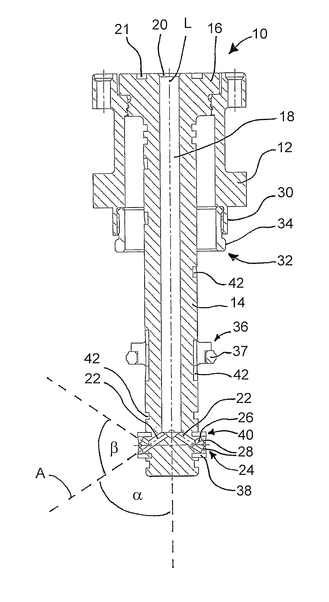
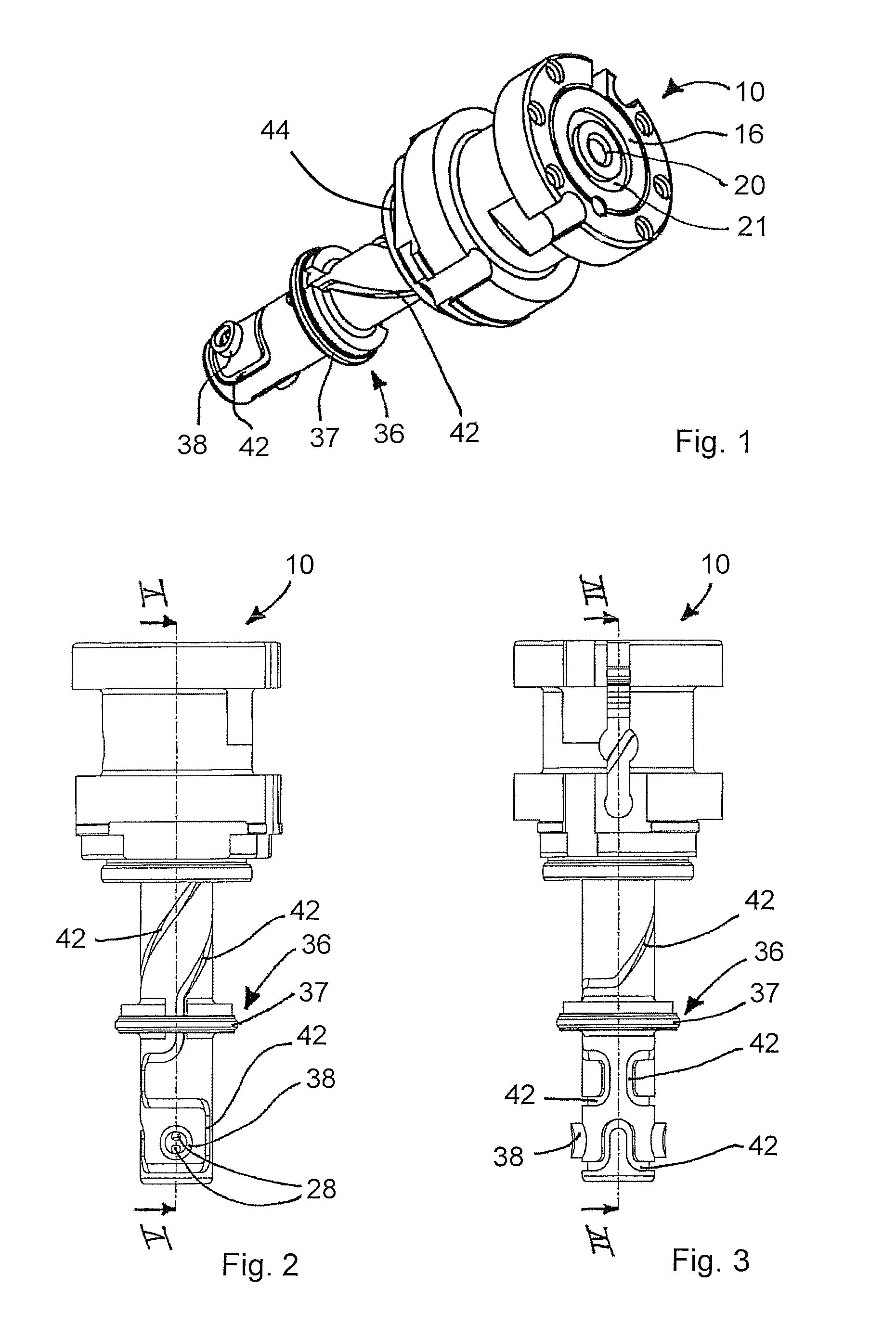
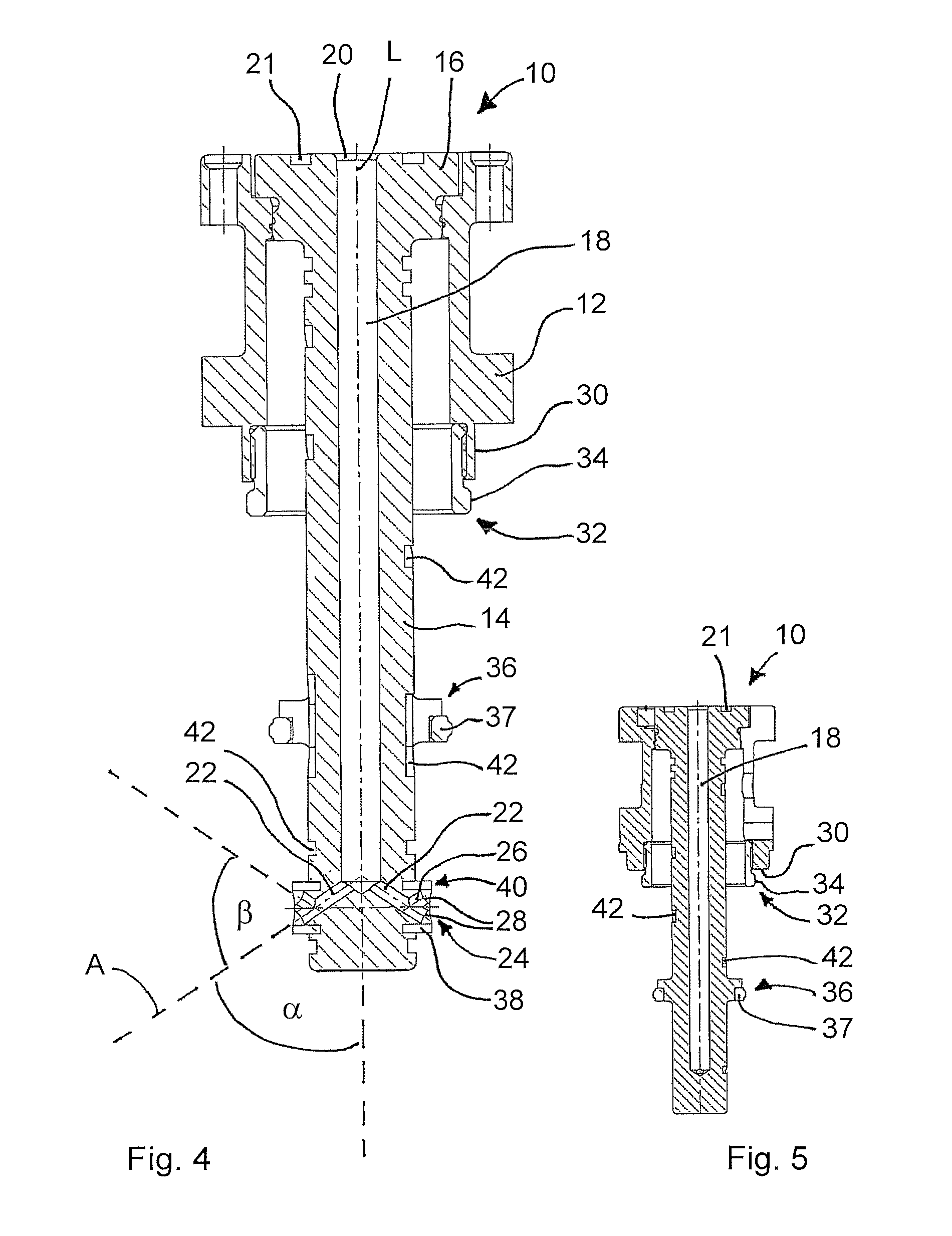
[0030]FIGS. 1 through 5 are different views of a preferred embodiment mode of an injection molding nozzle of the present invention denoted overall by the reference 10.

[0031]Said injection molding nozzle 10 is used in injection molding equipment making molded parts from a fluid processing material—for instance a plastic melt. Typically this omitted injection molding equipment comprises a mounting plate and a parallel manifold plate which subtends a system of flow ducts. Said flow ducts issue into several injection molding nozzles 10 illustratively in the form of hot runner nozzles, each nozzle being assembled by a housing 12 to the lower side of the manifold plate. In addition or alternatively, the nozzles 10 also may be mounted directly to the manifold (“TT” design).

[0032]Each injection molding nozzle 10 comprises a nozzle casing 14 which subtends a longitudinal axis L and which is fitted at its upper end with a flange-like hookup head 16. In the present instance the hookup head 16 ...


PUM

PropertyMeasurementUnit
angleaaaaaaaaaa
angleaaaaaaaaaa
thermal conductivityaaaaaaaaaa

Abstract

An injection molding nozzle (10) for injection molding equipment and comprising a nozzle casing (14) subtending a longitudinal axis (L) fitted with at least one flow duct (18) for a fluid processing material, further comprising at least one nozzle tip (24) discharging the fluid processing material out of the nozzle casing (14), the minimum of one nozzle tip (24) running transversely to the longitudinal axis (L) of the nozzle casing (14), the minimum of one nozzle tip (24) being integral with the nozzle casing (14).

Description

FIELD OF THE INVENTION[0001]The present invention relates to an injection molding nozzle.BACKGROUND ART[0002]Such nozzles are used in injection molding equipment to feed a fluid processing material at a predetermined temperature and under high pressure to a separable mold block respectively, to a mold insert. Most such nozzles comprise a tubular casing in the form of a feed pipe fitted with a flow duct for said fluid processing material and with a nozzle tip which is inserted terminally into said pipe and which subtends the discharge aperture of said flow duct.[0003]The state of the art contains the most diverse kinds of injection molding nozzles, in particular those used for edge gating. Most of these nozzles comprise a casing subtending at least one fluid processing material flow duct and at least one nozzle tip running perpendicularly to the longitudinal nozzle casing axis.[0004]Such an injection molding nozzle illustratively is known from the German patent document DE 196 18 960...

Claims


Application Information

Patent Timeline
Patent Type & Authority Patents(United States)
IPC IPC(8): B29C45/22
CPCB29C45/2735B29C45/278B29C2045/2761B29C2045/2779B29C2045/2783
Inventor GUNTHER, HERBERTSOMMER, SIEGRIDSCHNELL, TORSTEN
Owner GUENTHER HEISSKANALTECHNIK GMBH
Why Eureka
Try Eureka