Antenna system for communications on-the-move

a technology of satellite communications and antenna arrays, applied in the direction of antenna arrays, electrical devices, antenna adaptation in movable bodies, etc., can solve the problems of reducing the efficiency of the reflector system, and reducing the effective illumination of the surface area, so as to improve the robustness of the system, simplify the handling and integration of the vehicle, and high efficiency

Active Publication Date: 2012-08-21
OVZON SWEDEN AB
View PDF14 Cites 16 Cited by
  • Summary
  • Abstract
  • Description
  • Claims
  • Application Information

AI Technical Summary

Benefits of technology

[0007]The present invention is designed to address the above-mentioned needs. Embodiments of the present invention utilize a small antenna system for COTM in communication with a geostationary or geosynchronous satellite to and from a land mobile, maritime or airborne vehicle. The invention can improve the robustness of the system, and simplify handling and integration on the vehicle. The use of a high efficiency antenna also permits the use of a smaller aperture than required in a traditional reflector design.
[0008]Embodiments of systems and methods of the various aspects of the present invention mitigate (i.e., prevent, minimize, or otherwise diminish) RF losses customary in existing horn antennas. Embodiments also facilitate COTM by utilizing novel antenna configurations that tightly integrate RF (radio frequency) electronics while dissipating generated heat via an antenna compartment designed to function as a heat sink.
[0009]According to an embodiment of an aspect of the present invention, the antenna system comprises an antenna which receives signals from and transmits signals to a satellite. The antenna is powered by a power source, which may be a battery, conventional power line, generator, or other device. The antenna system also comprises radio frequency (“RF”) circuitry in communication with the antenna. The RF circuitry may comprise (a) a low-noise block (“LNB”) for receiving satellite signals; (b) a block up-converter (“BUC”) for transmission of satellite signals; and (c) a solid state power amplifier (“SSPA”) for amplifying received and transmitted signals. Any of these electronic or radiofrequency circuitry components may have any particular shape or configuration. In one embodiment, the LNB has dimensions of 100×30×20 mm, and the BUC / SSPA has dimensions of 100×80×25 mm. Examples of LNBs that may be used with the present invention are available from New Japan Radio Co., Ltd., model nos. NJR2535SC, NJR2536SC, and NJR2537SC. Examples of BUCs with components that may be used with the present invention are available from New Japan Radio Co., Ltd., model no. NJT5025 / 25F, and SNXP Ltd. In an embodiment of the invention, the RF electronics will be approximately 100×70×20 mm in size in order to minimize the amount of space necessary.

Problems solved by technology

This condition leads to lower efficiency in terms of gain relative to surface area.
There is also the blocking effect of mechanical obstacles that reduces the effective illumination of the surface area.
As the aperture dimension decreases, it becomes more difficult to maintain a high efficiency in the reflector system.
This is a result of the fact that illumination problems, irregularities, and blockage effects stay roughly constant while the reflector surface area decreases.

Method used


Image

  • Antenna system for communications on-the-move
  • Antenna system for communications on-the-move
  • Antenna system for communications on-the-move

Examples


Embodiment Construction

[0044]This description, including the figures, describes embodiments that illustrate various aspects of the present invention. These embodiments are not intended to, and do not, limit the scope of the invention to particular details.

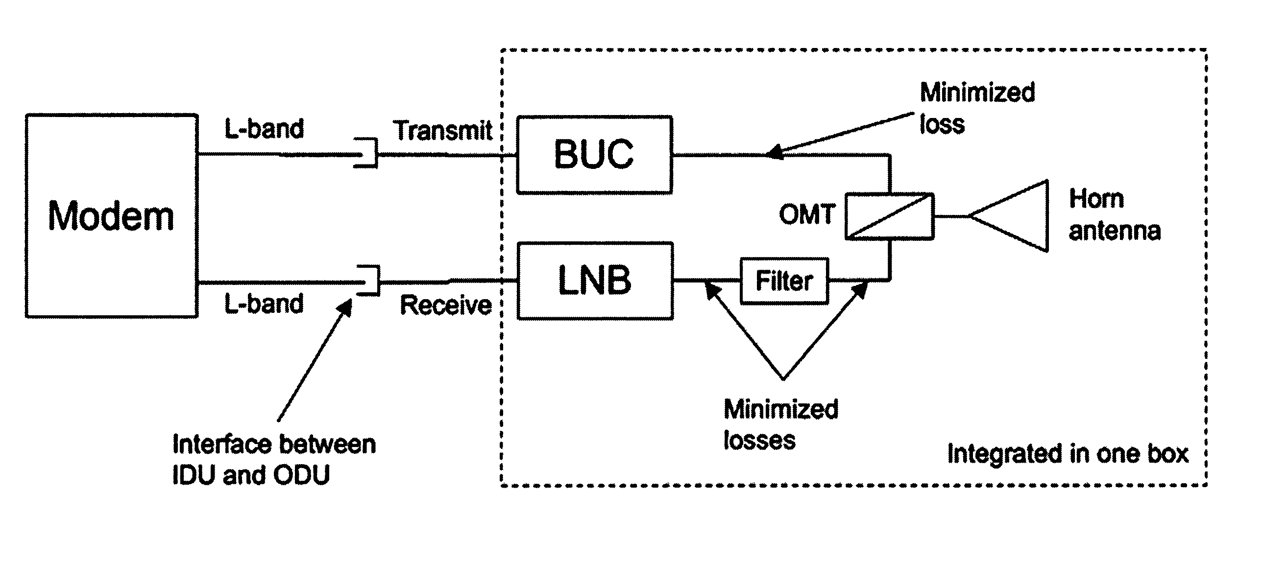
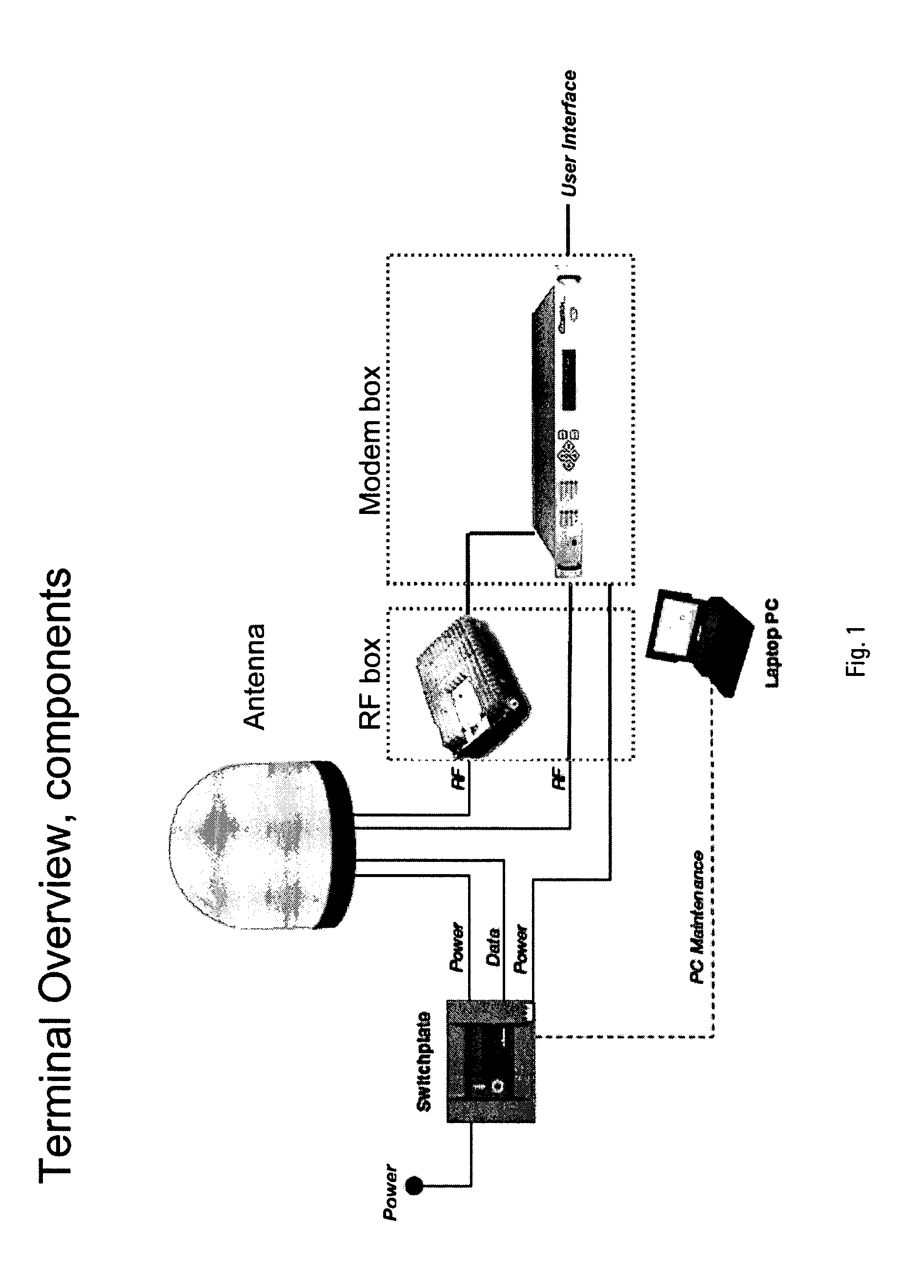
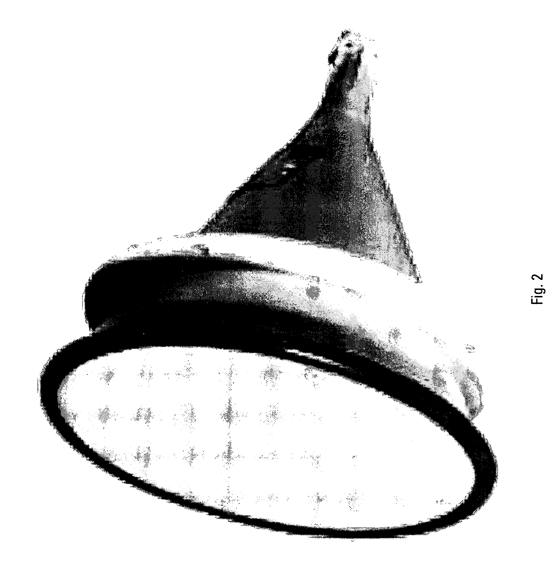
[0045]The present invention describes a small terminal used for COTM in communication with a geostationary or geosynchronous satellite to and from a land mobile, maritime or airborne vehicle. Various embodiments of aspects of the invention may improve system robustness and simplify handling and integration on the vehicle. The use of a high efficiency antenna makes it possible to use a smaller aperture than required in a traditional reflector design.

[0046]The features of the invention include, but are not limited to, the following highlights:[0047]Highly efficient antenna system to minimize system size;[0048]Minimization of RF losses internal to the system will reduce the required input power to the system and increase the system sensitivity (G / T defines ...


PUM


Abstract

A small antenna system for communications on-the-move (“COTM”) with a geostationary or geosynchronous satellite to and from a land mobile, maritime or airborne vehicle is disclosed. The antenna system provides a robust and simple means of establishing communications with a satellite or remote computer device. Further embodiments of systems and methods of the various aspects of the present invention mitigate RF losses customary in existing horn antennas. Embodiments also facilitate COTM by utilizing novel antenna configurations that tightly integrate RF electronics while dissipating generated heat via an antenna compartment that may be designed to function as or be used in conjunction with a heat sink.

Description

[0001]This application claims the priority benefit of U.S. provisional patent application Ser. No. 60 / 972,173, filed on Sep. 13, 2007, the contents of which are incorporated herein in their entirety by reference.FIELD OF THE INVENTION[0002]This invention relates to antenna systems for satellite communications.BACKGROUND OF THE INVENTION[0003]Operating satellite communications on-the-move (“COTM”) requires an antenna system that is compact and reliable in order to facilitate mobile field operations. FIG. 1 illustrates the principal building blocks of a conventional on-the-move terminal. FIG. 1 shows an arrangement of parts typically used to form an on-the-move terminal for satellite communications. Here the antenna is housed inside the radome, and the RF box connected to this radome is the transmitter.[0004]In a traditional reflector antenna, a horn illuminates the reflector surface. To minimize the spill-over effect, the horn is adjusted such that the intensity gradually decreases t...

Claims


Application Information

Patent Timeline
Patent Type & Authority Patents(United States)
IPC IPC(8): H01Q3/00
CPCH01Q1/02H01Q1/28H01Q1/32H01Q1/34H01Q3/08H01Q13/0258H01Q21/064
Inventor WAHLBERG, PERLEJNELL, KENNET
Owner OVZON SWEDEN AB
Why Eureka
Try Eureka