Balloon inflator

a balloon inflator and balloon technology, applied in the field of balloon inflators, can solve the problems of high temperature problem, failure to provide a single balloon inflator unit that can safely fill multiple types of balloons, and quick wear of the motor of such inflators,

Active Publication Date: 2012-08-28
PREMIUM BALLOON ACCESSORIES
View PDF15 Cites 10 Cited by
  • Summary
  • Abstract
  • Description
  • Claims
  • Application Information

AI Technical Summary

Problems solved by technology

As a result, the motors of such inflators are given to quick wear-out after operating at continuously high temperatures.
While such pressures are suitable for most latex balloons and small foil balloons lacking self-sealing valves, it has been found that these pressures can force the self-sealing valve out of the neck of a large foil balloon.
Thus, the prior art has failed to provide a single balloon inflator unit that can safely fill multiple types of balloons, including particularly latex balloons, small foil balloons, and large foil balloons including self-sealing valves.
Additionally, the prior art balloon inflator of U.S. Pat. No. 5,199,847 has been found to suffer from the high temperature problem previously disclosed herein.
That is, despite of the employment of a bypass motor, continuous operation of the prior art balloon inflator can result in a raising of the bypass motor temperature to a point where the air filling the balloons is too warm, and, as a result, there is still a potential for balloons to deflate to some extent after the initial inflation.
This movable nozzle was provided to aid in keeping the operating temperature down by limiting the amount of resistance encountered by the fan motor, but it has been found still to be too restrictive since the air to be exhausted must still travel through the housing to exit at the bottom exhaust.

Method used


Image

  • Balloon inflator
  • Balloon inflator
  • Balloon inflator

Examples


Embodiment Construction

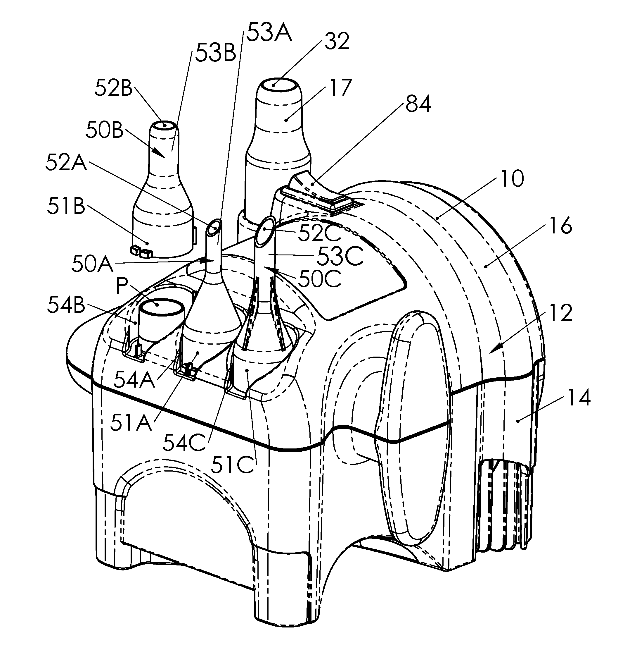
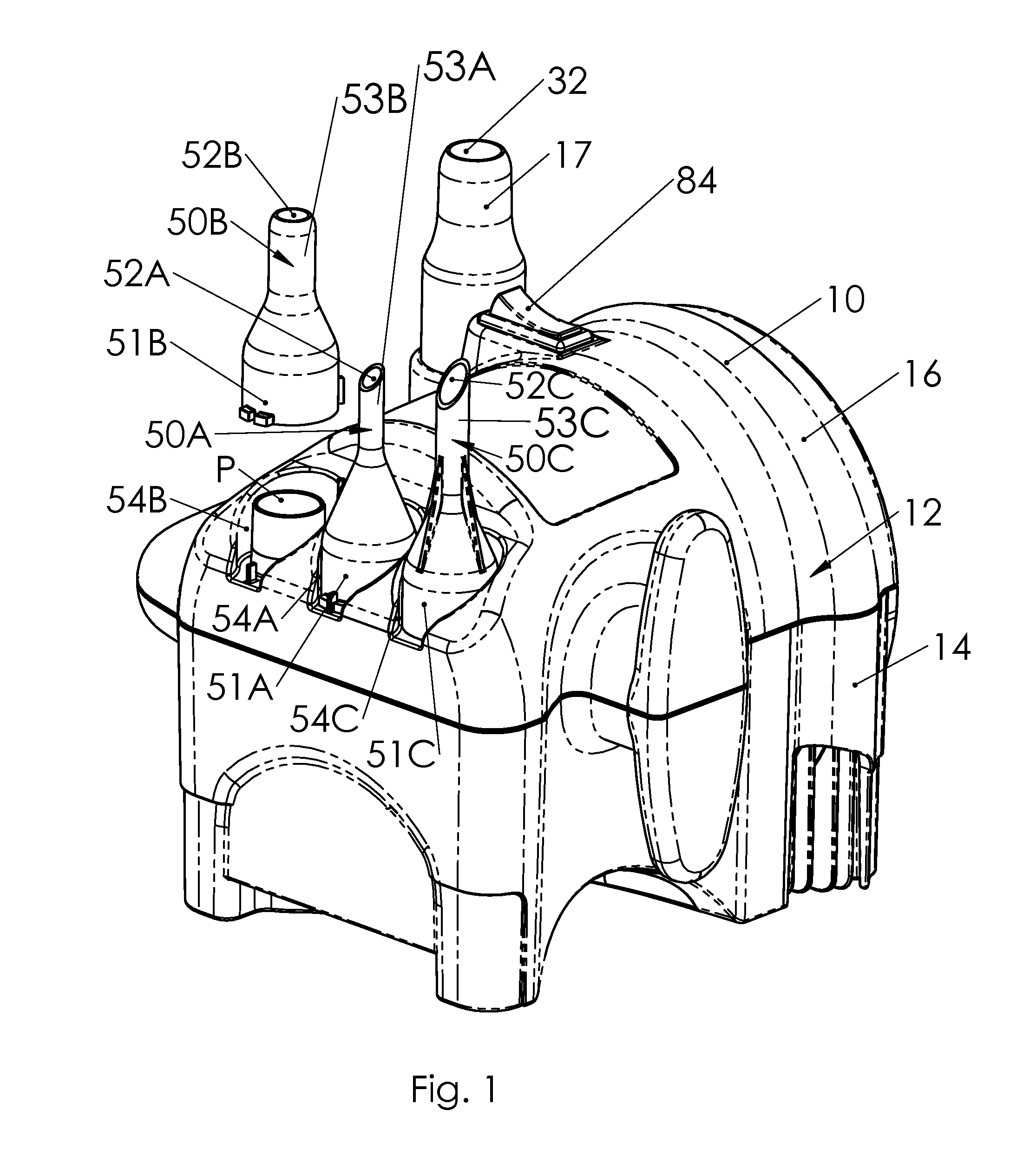
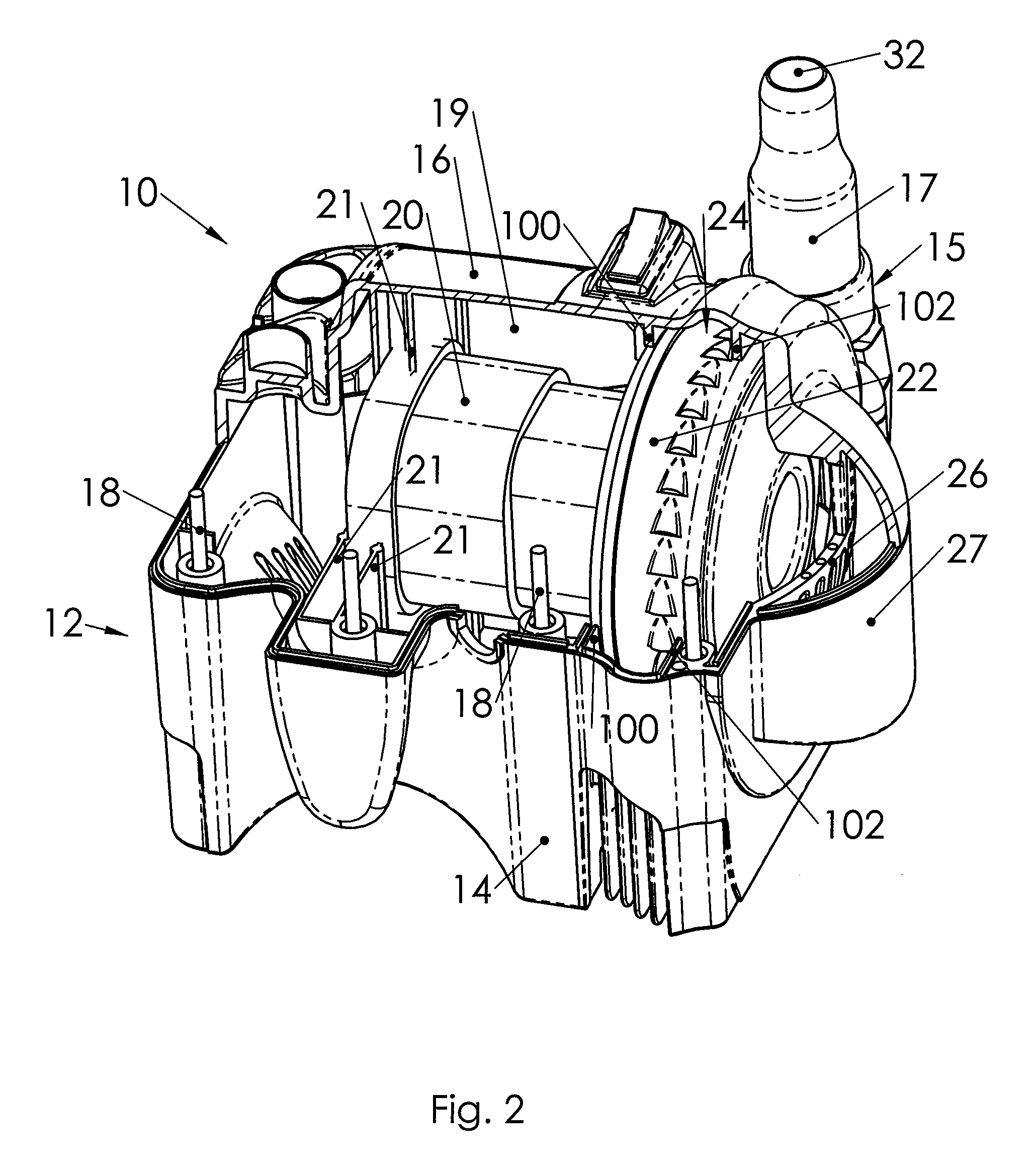
[0023]Referring now to the drawings and more particularly FIGS. 1-3, it can be seen that a balloon inflator according to this invention is designated generally by the numeral 10. As shown, the balloon inflator 10 includes a housing 12, which may be of any suitable material and construction. Preferably, and in accordance with a most preferred embodiment, the housing 12 is formed of two halves, a first housing portion 14 and a second housing portion 16, and an inflation nozzle 17. The first housing portion 14 and the second housing portion 16 are joined by interaction of male members 18 and appropriately shaped and positioned female members (not shown) that receive male members 18. Such construction facilitates manufacturing and assembly. By way of example only, male members 18 may be screw fasteners mating with threaded bores (female members) on second housing portion 16. The inflation nozzle 17 is received in a nozzle receipt portion 15 of the joined first and second housing portion...


PUM

PropertyMeasurementUnit
power levelaaaaaaaaaa
temperatureaaaaaaaaaa
temperaturesaaaaaaaaaa

Abstract

A balloon inflator includes a nozzle adaptor configured to fit over an outlet of an inflation nozzle. A nozzle receipt is provided by the balloon inflator housing to selectively receive the nozzle adaptor and a switch is provided at the nozzle receipt. The nozzle adaptor is adapted to trigger the switch when received at the nozzle receipt. The switch controls the power supplied to the motor, such that different motor operating parameters are realized when the switch is triggered and when the switch is not triggered. In a particular embodiment, the nozzle adaptor includes vent channels that exhaust a portion of the air to the atmosphere when a balloon is fitted over the alternate outlet.

Description

TECHNICAL FIELD[0001]The invention herein resides in the art of inflation devices and relates to a balloon inflator that employs a bypass motor having separate working air and motor cooling air paths. The invention further relates to a balloon inflator having a fill nozzle and a plurality of adaptors that fit on said fill nozzle to fill different types of balloons. The invention also relates to a balloon inflator having at least one switch actuated by at least one adaptor in order to change the operating parameters of the balloon inflator.BACKGROUND ART[0002]Various types of balloon inflators have previously been known. Typically, such inflators incorporate a through-flow motor which draws air from the surrounding atmosphere and exhausts it through an air duct providing an inflation nozzle adapted to receive the neck of a balloon. Accordingly, the air used for inflating the balloon is the same air that is drawn through the motor to cool it. As the motor works, its temperature rises....

Claims


Application Information

Patent Timeline
Patent Type & Authority Patents(United States)
IPC IPC(8): B65B1/04F01D17/12
CPCA63H27/10A63H2027/1033A63H2027/1083
Inventor NELSON, DAVID C.MELUCH, MARTIN A.MELUCH, VALENT L.SCHROEDER, WESLEY A.
Owner PREMIUM BALLOON ACCESSORIES
Why Eureka
Try Eureka