
Circuits for harvesting energy from piezoelectric devices

a piezoelectric device and circuit technology, applied in the field of apparatus for harvesting energy, can solve problems such as strain on piezoelectric materials

Inactive Publication Date: 2012-08-28
PAR TECH
View PDF7 Cites 31 Cited by
  • Summary
  • Abstract
  • Description
  • Claims
  • Application Information

AI Technical Summary

Benefits of technology

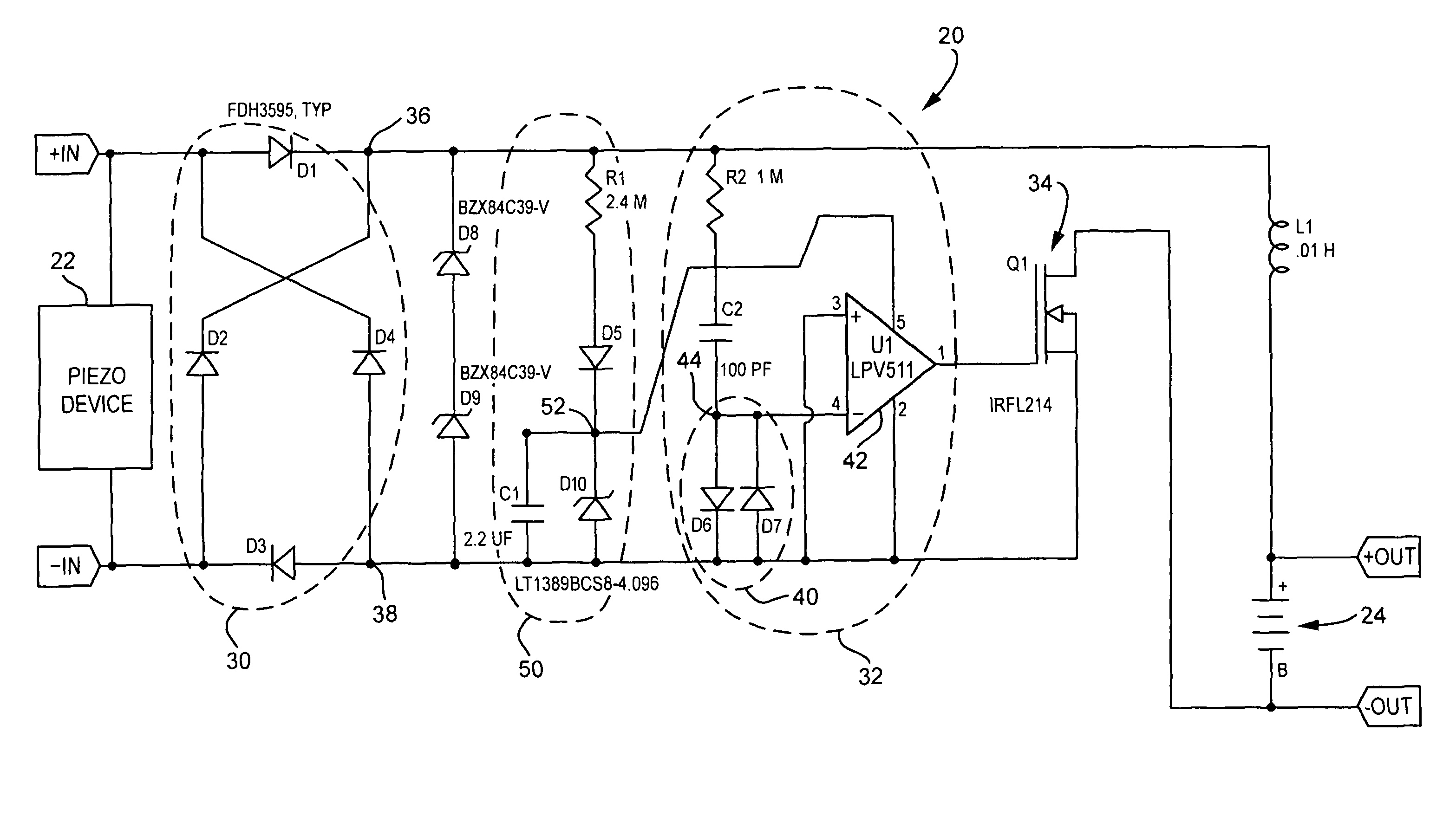
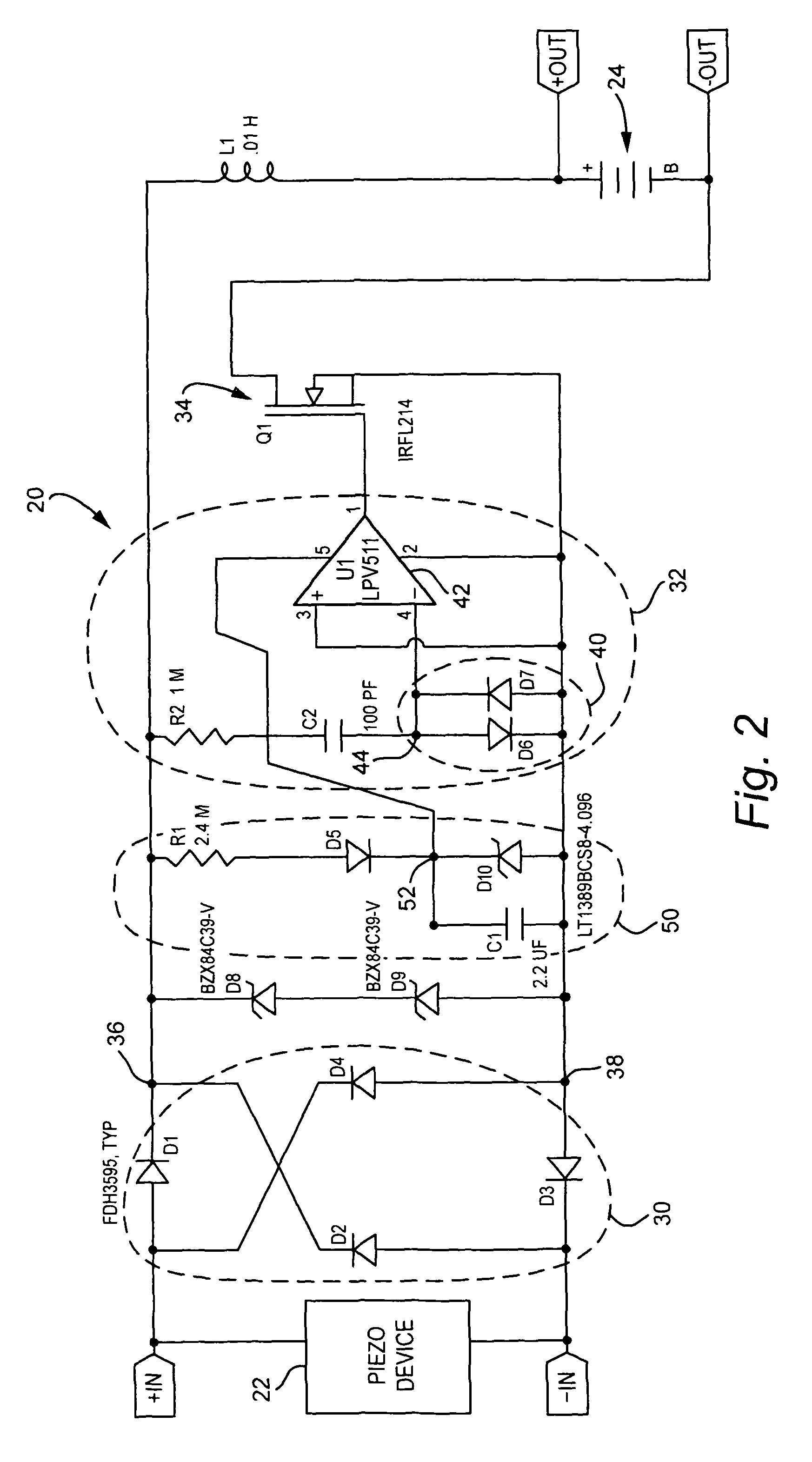
"The technology described in this patent relates to circuits that use a piezoelectric device to charge a charge storage device. The circuits have a peak detector that detects the peak voltage across the piezoelectric device and a switch that initiates the transfer of electrical charge from the piezoelectric device to the charge storage device upon detection of the peak voltage. The peak detector comprises a peak-detection capacitance and a non-linear PN junction circuit that turns off the switch when the peak-detection capacitance is charging and turns on the switch when the peak-detection capacitance is discharging. The circuits can also have a charge multiplier circuit that continues to apply the electrical charge after the switch has been turned off and a detector that can detect both positive and negative peak voltage across the piezoelectric device. The technology also includes options for bidirectional control of energy flow and collecting increased charge from the piezoelectric device in an energy storage device."

Problems solved by technology

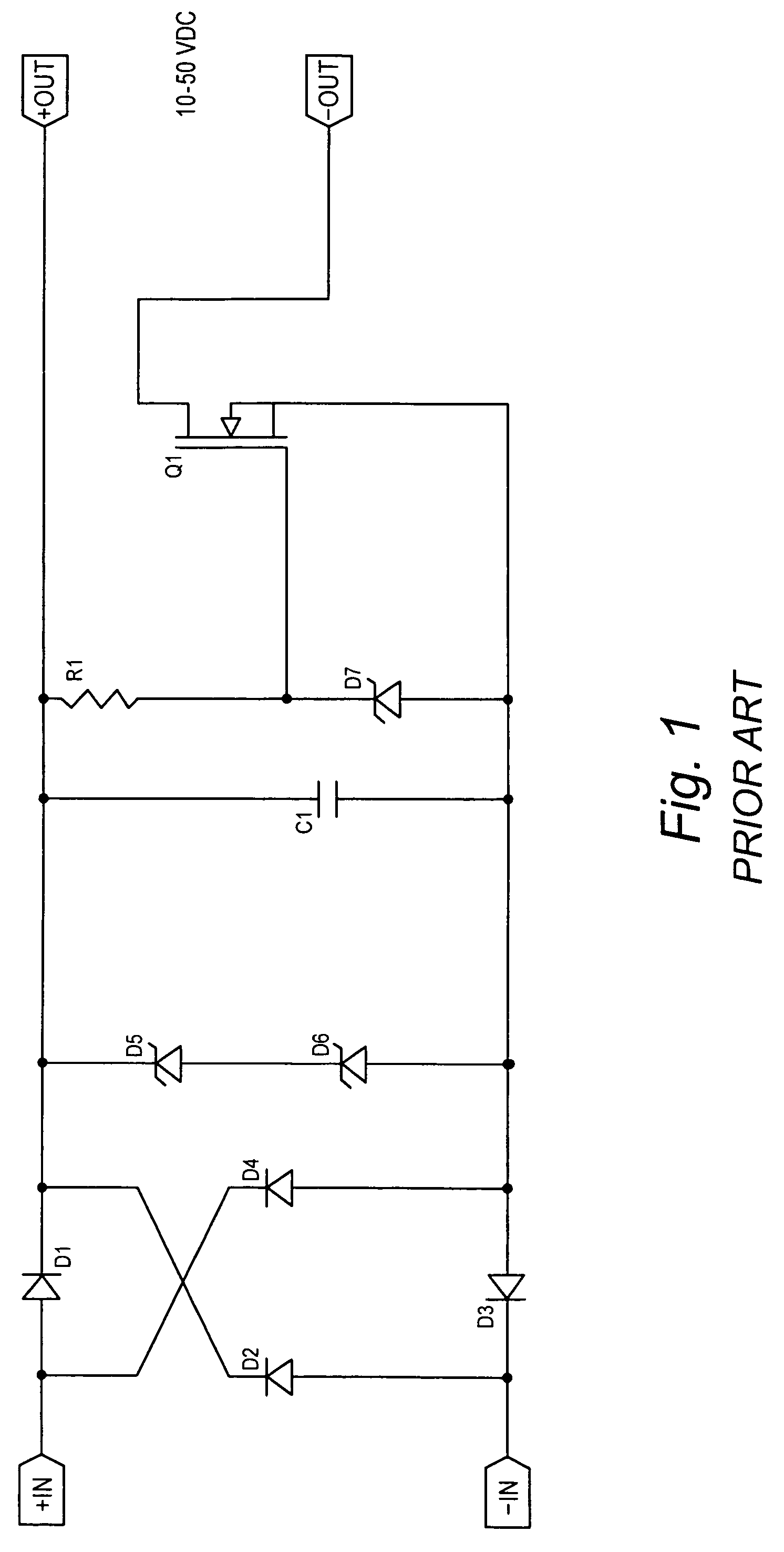
The strain on the piezoelectric material can result from various factors, such as vibration or even change of temperature (heating and cooling) of the piezoelectric material.

Method used


Image

  • Circuits for harvesting energy from piezoelectric devices
  • Circuits for harvesting energy from piezoelectric devices
  • Circuits for harvesting energy from piezoelectric devices

Examples


Embodiment Construction

[0032]In the following description, for purposes of explanation and not limitation, specific details are set forth such as particular architectures, interfaces, techniques, etc. in order to provide a thorough understanding of the present invention. However, it will be apparent to those skilled in the art that the present invention may be practiced in other embodiments that depart from these specific details. That is, those skilled in the art will be able to devise various arrangements which, although not explicitly described or shown herein, embody the principles of the invention and are included within its spirit and scope. In some instances, detailed descriptions of well-known devices, circuits, and methods are omitted so as not to obscure the description of the present invention with unnecessary detail. All statements herein reciting principles, aspects, and embodiments of the invention, as well as specific examples thereof, are intended to encompass both structural and functiona...


PUM


Abstract

Circuits (20, 220, 320, 420) are provided for applying electrical charge collected from a piezoelectric device (22) to a charge storage device (24, 224, 424). The circuits comprise a peak detector (32, 232) and a switch(es) (34, 134, 234, 434) which is / are operated to initiate transfer of the electrical charge from the piezoelectric device to the charge storage device upon detection by the peak detector (32, 232) of a peak voltage across the piezoelectric device (22). In an example embodiment, the peak detector (32, 232) comprises a peak-detection capacitance (C4); a gain element (42, 242); and a non-linear PN junction circuit (40). The circuits can also comprise charge multiplier circuit (300) configured to continue application of the electrical charge to the charge storage device (224) after the switch (262) has been turned off and / or after a point in time when magnitude of the voltage across the charge storage device (224) equals the magnitude of the voltage across the piezoelectric device (22).

Description

[0001]This application claims the priority and benefit of U.S. provisional patent application 61 / 035,610, filed Mar. 11, 2008, entitled “Active Energy Extraction Circuit for Energy Harvesting”, which is incorporated herein by reference in its entirety.BACKGROUND[0002]I. Technical Field[0003]This invention pertains to the harvesting or recycling of energy, and particularly energy harvesting in apparatus which involve or comprise piezoelectric element(s).[0004]II. Related Art and Other Considerations[0005]A piezoelectric element is essentially a parallel plate capacitor with a dielectric material between the plates (the piezoceramic). As the piezoceramic material is strained, a charge builds up on the electrodes (plates). The strain on the piezoelectric material can result from various factors, such as vibration or even change of temperature (heating and cooling) of the piezoelectric material.[0006]If the goal is to achieve the maximum energy transfer from a piezogenerator, then it is...

Claims


Application Information

Patent Timeline
Patent Type & Authority Patents(United States)
IPC IPC(8): H01L41/08H02N2/18H10N30/00
CPCH02J7/32H02N2/181
Inventor WRIGHT, DAVID D.
Owner PAR TECH
Learn More