
Paper feeding apparatus and image forming apparatus

a technology of paper feeding apparatus and paper forming apparatus, which is applied in the direction of electrographic process, instruments, transportation and packaging, etc., can solve the problems of false image formation or improper transportation, false image such as black lines, and difficulty in removing paper dust from the edges of paper in a width direction,

Inactive Publication Date: 2012-09-04
MURATA MASCH LTD
View PDF8 Cites 0 Cited by
  • Summary
  • Abstract
  • Description
  • Claims
  • Application Information

AI Technical Summary

Benefits of technology

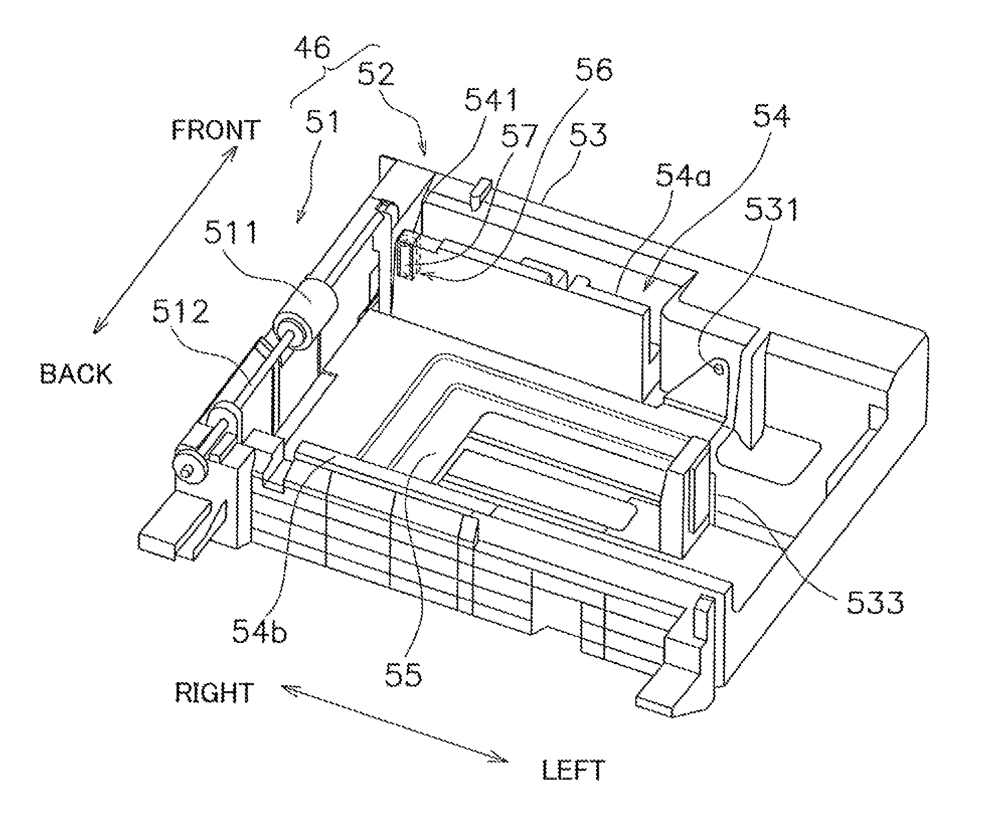
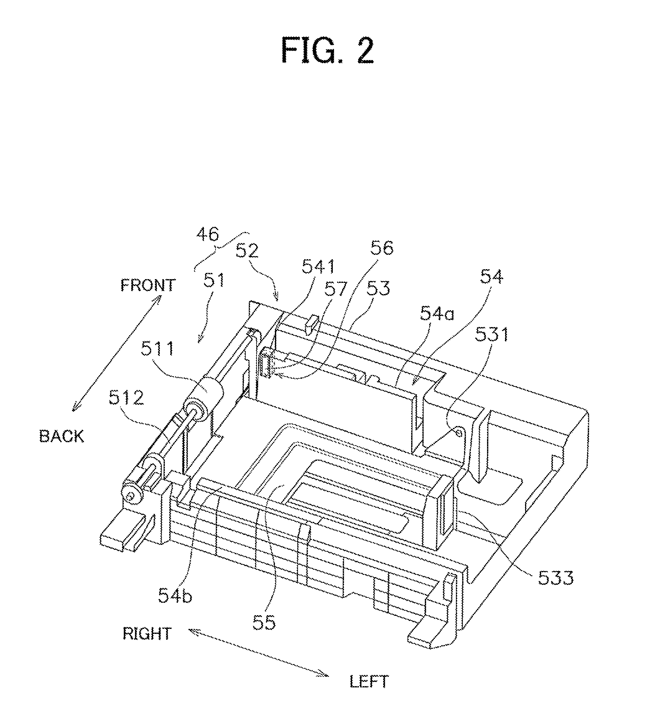
The present invention provides a paper feeding apparatus and an image forming apparatus that can effectively remove dust adhered to paper. By using a dust removing roller in the guide member of the paper feeding apparatus, dust adhered to the edges of paper in the width direction can be removed, preventing it from getting into the image forming unit of the image forming apparatus. The dust removing roller is preferably a conductive roller that can easily attract and remove dust from the paper. The paper feeding apparatus also includes a blade member and a dust containing member to securely contain dust removed from the roller surface. The technical effects of the present invention are to improve the quality of printed documents by removing dust from the paper and to prevent dust from getting into the image forming unit of the image forming apparatus.

Problems solved by technology

Such an image forming apparatus causes false image formation or improper transportation when foreign substances such as paper dust are adhered to the paper.
For example, when paper dust is adhered to a photosensitive drum of an image forming unit, it will interfere with forming an electrostatic latent image on the photosensitive drum, and cause false images such as black lines.
However, as described above, paper dust produced during the cutting process is often found on edges of the paper in a width direction, including surfaces of the portions having gone through the cut.
Therefore, it is difficult to sufficiently remove paper dust adhered to edges of paper in a width direction simply by arranging a roller in contact with the surface of paper.

Method used


Image

  • Paper feeding apparatus and image forming apparatus
  • Paper feeding apparatus and image forming apparatus
  • Paper feeding apparatus and image forming apparatus

Examples


Embodiment Construction

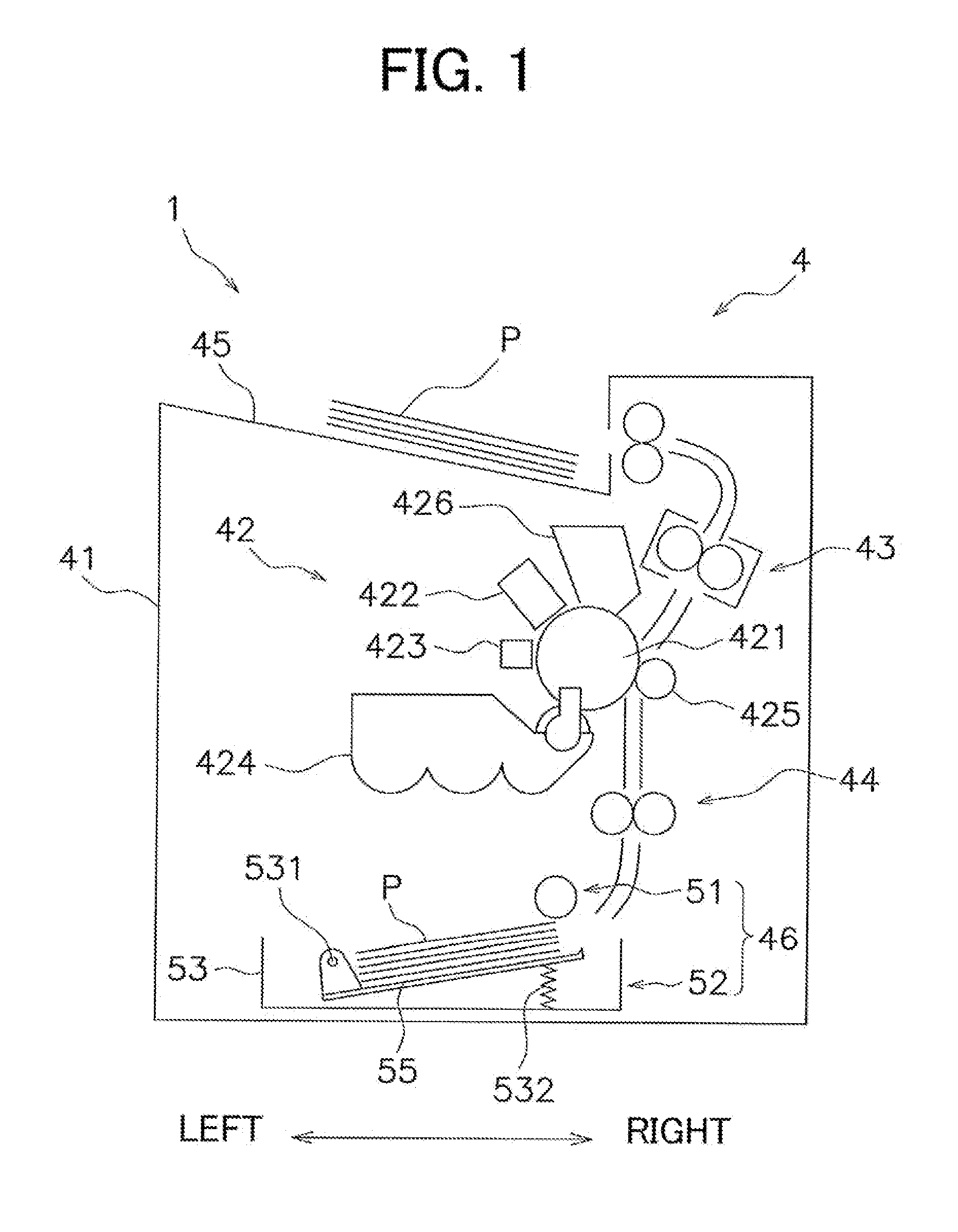
[0026]In one preferred embodiment of the present invention, an image forming apparatus preferably used as a printer, for example, will be described with reference to FIG. 1. FIG. 1 is a view which illustrates a configuration of an image forming apparatus. An image forming apparatus 1 preferably includes a chassis 41, in which an image forming unit 42, a fusing unit 43, a paper transportation unit 44, a paper ejecting unit 45 and a paper feeding apparatus 46 are provided. Hereinafter, to clarify the relationship between each direction with respect to the image forming apparatus 1, a direction in which paper in the paper feeding apparatus 46 is transported is regarded as a longitudinal or transport direction, and a direction perpendicular or substantially perpendicular to the horizontal direction which indicates the back and the front of the apparatus is regarded as a width direction.

[0027]An image forming unit 42, for example, forms images on paper P according to an image data transm...


PUM

PropertyMeasurementUnit
electrical potentialaaaaaaaaaa
pressureaaaaaaaaaa
widthaaaaaaaaaa

Abstract

A paper feeding apparatus transports paper one by one through a transportation mechanism to an image forming unit of an image forming apparatus. The paper feeding apparatus includes a paper feed cassette to contain paper, a paper side guide arranged in the paper feed cassette to position the paper in a direction perpendicular or substantially perpendicular to a transport direction of the paper, and a dust removing roller arranged in the paper side guide and in contact with the paper contained in the paper feed cassette.

Description

CROSS-REFERENCE TO RELATED APPLICATIONS[0001]This application claims priority under 35 U.S.C. 119 to Japanese Patent Application No. 2010-034267, filed on Feb. 19, 2010, which application is hereby incorporated by reference in its entirety.BACKGROUND OF THE INVENTION[0002]1. Field of the Invention[0003]The present invention relates to a paper feeding apparatus configured to transport paper to an image forming unit of an image forming apparatus and an image forming apparatus including a paper feeding apparatus.[0004]2. Description of the Related Art[0005]An image forming apparatus, such as a copier, a facsimile machine, a multi-function peripheral, includes a paper feeding unit which transports paper to an image forming unit. A paper feeding unit includes a paper feed cassette and a pick up mechanism. For example, through the pick up mechanism, paper in the paper feed cassette is transported to a transportation path. And then, the paper is transported to the image forming unit.[0006]...

Claims


Application Information

Patent Timeline
Patent Type & Authority Patents(United States)
IPC IPC(8): B65H1/00
CPCB65H1/266B65H3/66B65H3/56B65H2404/70B65H2405/1142B65H2404/561B65H2301/5133G03G15/00
Inventor TAKAMATSU, NARITOSHI
Owner MURATA MASCH LTD
Learn More