Socket for pipe joint and pipe joint

Active Publication Date: 2012-09-04
NITTO KOHKI CO LTD
View PDF46 Cites 21 Cited by
  • Summary
  • Abstract
  • Description
  • Claims
  • Application Information

AI Technical Summary

Benefits of technology

[0011]An object of the present invention is to solve the above-described problems of the conventional pipe joints and to provide a socket free from leakage either when the plug is connected to or disconnected from the socket, and also provide a pipe joint having the socket of the present invention.
[0013]In the socket according to the present invention, the displacement of the collar takes place after the locking element-pushing portion has pushed out the plug-locking element to displace the sleeve rearward, thereby releasing the sleeve-operating element from the press engagement with the sleeve. That is, in a case where the movable valve member is contiguously connected to the collar as in the pipe joint according to the above-described prior art, for example, the displacement of the movable valve member takes place after the sleeve-operating element has been released from the press engagement with the sleeve. If the plug is suddenly pulled out in such a state, the sleeve-operating element offers substantially no resistance to the displacement of the collar because the sleeve-operating element is not in press engagement with the sleeve. Accordingly, the collar can be rapidly returned to the first position (position assumed by the collar before it is displaced) by the forward urging force applied thereto. Therefore, it is possible to prevent the problem of fluid leakage even in a case where the movable valve member is contiguously connected to the collar as stated above.
[0015]In the socket of the present invention, the guide portion (16) may be an annular projection projecting from the inner peripheral surface of the socket body (10) and having a smaller inner diameter than that of the collar (30). This is for preventing the forward end edge of the plug from engaging with the collar even more reliably.
[0016]Further, the socket of the present invention may further include a fixed valve member (17) fixed at its rear end to the socket body (10) to extend forward along the axial direction of the socket body (10) and having a valve head at its forward end, and an annular movable valve member (31) longitudinally slidable along the inner peripheral surface of the socket body (10) and urged forward to sealingly engage with the valve head (17a). In this case, the collar (30) extends forward from the forward end surface of the movable valve member (31). With this structure, when the collar is moved rearward, the movable valve member (31) is moved rearward to separate from the valve head of the fixed valve member (17), thus canceling the sealing engagement. By virtue of this structure, even if the plug is suddenly pulled out after the collar has been moved rearward, the collar can immediately return to the original first position, and hence the movable valve member can also return into sealing engagement with the valve head of the fixed valve member to prevent leakage of fluid.
[0018]In addition, the present invention provides a pipe joint including the socket (1) of the present invention and the plug (5) that is inserted and connected to the socket (1). In the pipe joint, the collar (30) is pushed in to the second position by the plug (5) inserted in the collar (30) after the plug-locking element (14) has reached the position for preventing forward displacement of the sleeve (20). This pipe joint eliminates leakage when connecting and disconnecting the plug.

Problems solved by technology

If the plug is suddenly pulled out in such a state, the sleeve-operating element offers substantially no resistance to the displacement of the collar because the sleeve-operating element is not in press engagement with the sleeve.

Method used


Image

  • Socket for pipe joint and pipe joint
  • Socket for pipe joint and pipe joint
  • Socket for pipe joint and pipe joint

Examples


Embodiment Construction

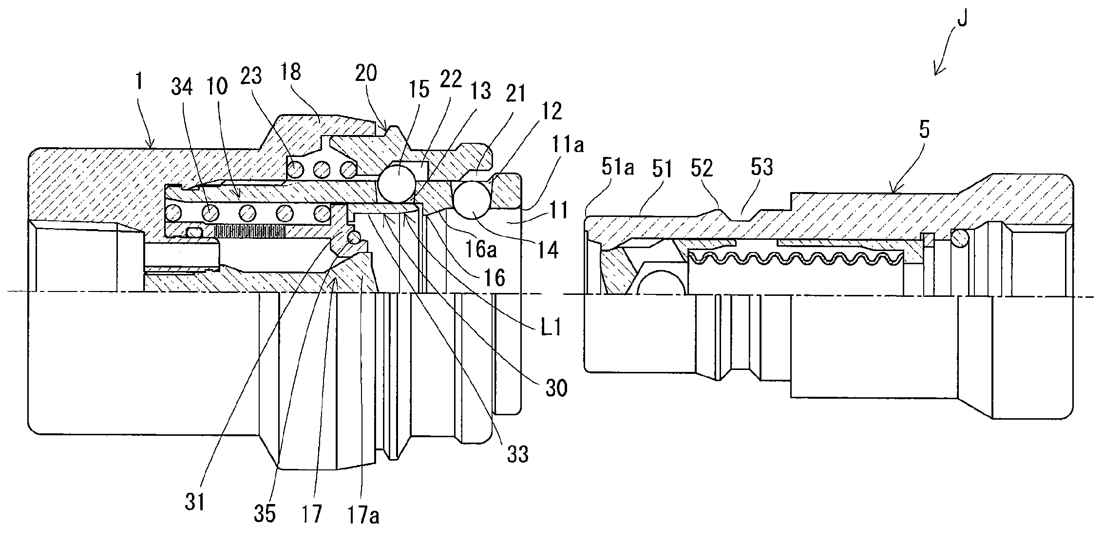
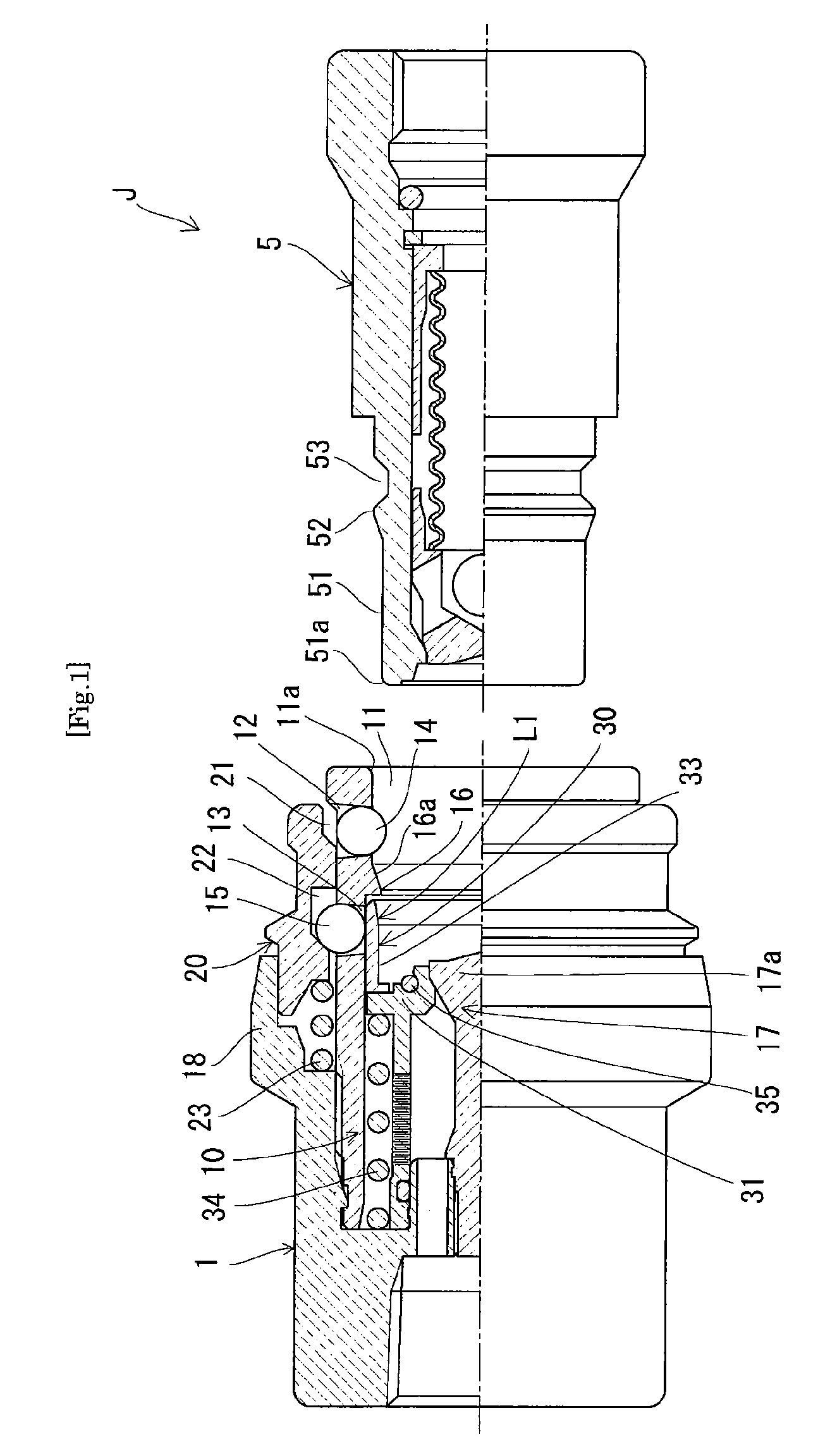
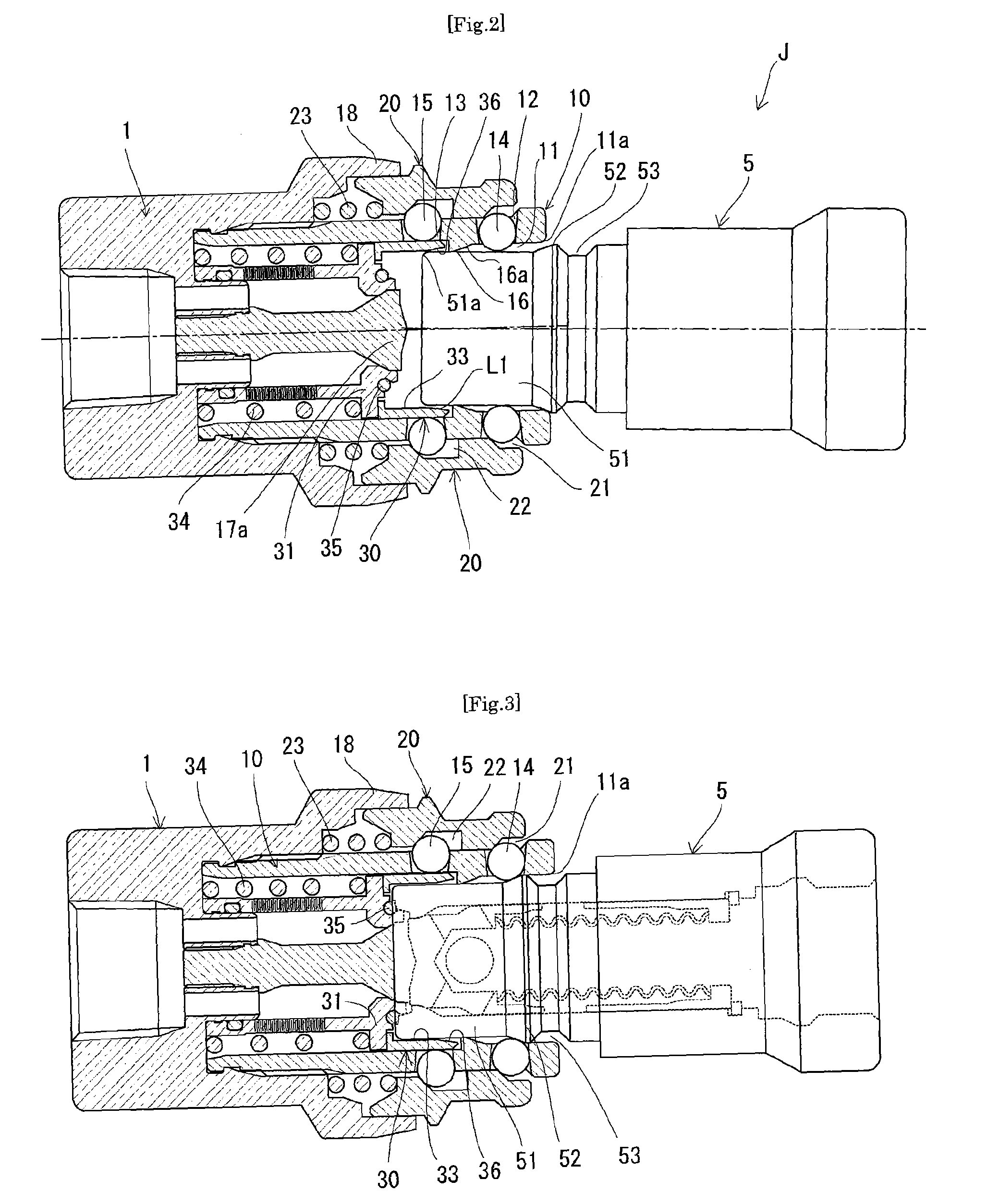
[0027]As shown in FIGS. 1 to 5, a pipe joint J according to the present invention comprises a socket 1 and a plug 5.

[0028]The plug 5 has an insert part 51 with a predetermined diameter extending rearward from the forward end of the plug 5, a locking element-pushing portion 52 provided contiguously with the insert part 51 and having a larger diameter than that of the insert part 51, and a locking recess 53 provided contiguously with the locking element-pushing portion to receive a plug-locking element 14 (described later) to lock the plug 5 to the socket 1.

[0029]The socket 1 has a cylindrical socket body 10, a sleeve 20 provided around the socket body 10 displaceably in the longitudinal direction of the socket body 10 and urged forward by a spring 23, and a collar 30 provided in the socket body 10 slidably in the longitudinal direction of the socket body 10 and urged forward by a spring 34.

[0030]The socket body 10 has a plug-receiving part 11 that is open forward to receive the plug,...


PUM


Abstract

A socket that receives and locks a plug has a cylindrical socket body, a plug-locking element provided in a first through-hole of the socket, a sleeve-operating element provided in a second through-hole of the socket, a sleeve, and a collar. The collar is movable between a first position (FIG. 1) and a second position where the collar allows radially inward displacement of the sleeve-operating element by the plug inserted into the socket. When the plug is inserted into the socket, first, a locking element-pushing portion of the plug pushes out the plug-locking element into a first recess of the sleeve and causes the plug-locking element to displace the sleeve rearward. As the plug is further inserted into the socket in this state, the plug engages and pushes the collar from the first position to the second position.

Description

RELATED APPLICATIONS[0001]This application is a continuation of PCT / JP2009 / 053710 filed on Feb. 27, 2009, which claims priority to Japanese Application No. 2008-047572 filed on Feb. 28, 2008. The entire contents of these applications are incorporated herein by reference.TECHNICAL FIELD[0002]The present invention relates to a socket of a pipe joint used by inserting a plug into the socket and also relates to such a pipe joint. More particularly, the present invention relates to what is called a one-touch connection type pipe joint comprising a socket and a plug that can be connected to each other simply by inserting the plug into the socket. The present invention also relates to a socket for use in such a pipe joint.BACKGROUND ART[0003]With a one-touch connection pipe joint, simply inserting a plug (male joint member) into a socket (female joint member) causes a spherical locking element of the socket to engage with a locking recess formed on the outer surface of the plug inserted, t...

Claims


Application Information

Patent Timeline
Patent Type & Authority Patents(United States)
IPC IPC(8): F16L37/00
CPCF16L37/23F16L37/34
Inventor TAKAHASHI, MASAKI
Owner NITTO KOHKI CO LTD
Why Eureka
Try Eureka