Eureka AIR delivers breakthrough ideas for toughest innovation challenges, trusted by R&D personnel around the world.

Orthodontic appliance

Inactive Publication Date: 2012-09-04
PLOWMAN PAUL E
View PDF29 Cites 7 Cited by
  • Summary
  • Abstract
  • Description
  • Claims
  • Application Information

AI Technical Summary

Benefits of technology

[0006]In accordance with the preferred embodiments, an orthodontic appliance (“dental appliance”) that includes at least a first member. The first member having a first sloped surface and is configured to attach to a tooth. In a preferred embodiment, a second member has a second sloped surface and is configured to attach to a tooth. The sloped surface of the second member preferably interacts with the sloped surface of the first member to correct mandibular disharmony. Further in a preferred embodiment, the first and second members each have a laterally extending extraction feature extending from a main body portion. The laterally extending extraction features facilitate separation of the first and second members from the patient's teeth.

Problems solved by technology

The lack of an efficient appliance to correct dental disharmonies results from the complexity of installation, use, and removal of the corrective appliance.
With numerous pieces and precise locations in a mouth, common corrective appliances require operational harmony that is difficult to achieve for long periods due to everyday activities of a patient such as eating.
Similarly, large corrective apparatus create occupational problems such as speaking and swallowing.
However, none of the disclosed appliances provide an efficient method of installation, use, and removal that allows the patient to maintain a level of everyday activity.
The U.S. Pat. No. 7,018,203 uses angled surfaces to correct class II malocclusion, but uses large “removable” components that require numerous connection features that restrict movement of the mouth unnecessarily.
Moreover, U.S. Pat. No. 6,604,527 advances a mandible, but occupies all the teeth in the mouth which restricts a patient's ability to where the apparatus continually.
Therefore, attempts have been made to correct mandibular disharmonies, but have failed to provide an appliance that is installed, used, and removed in a simple and efficient manner.

Method used


Image

  • Orthodontic appliance
  • Orthodontic appliance
  • Orthodontic appliance

Examples


Embodiment Construction

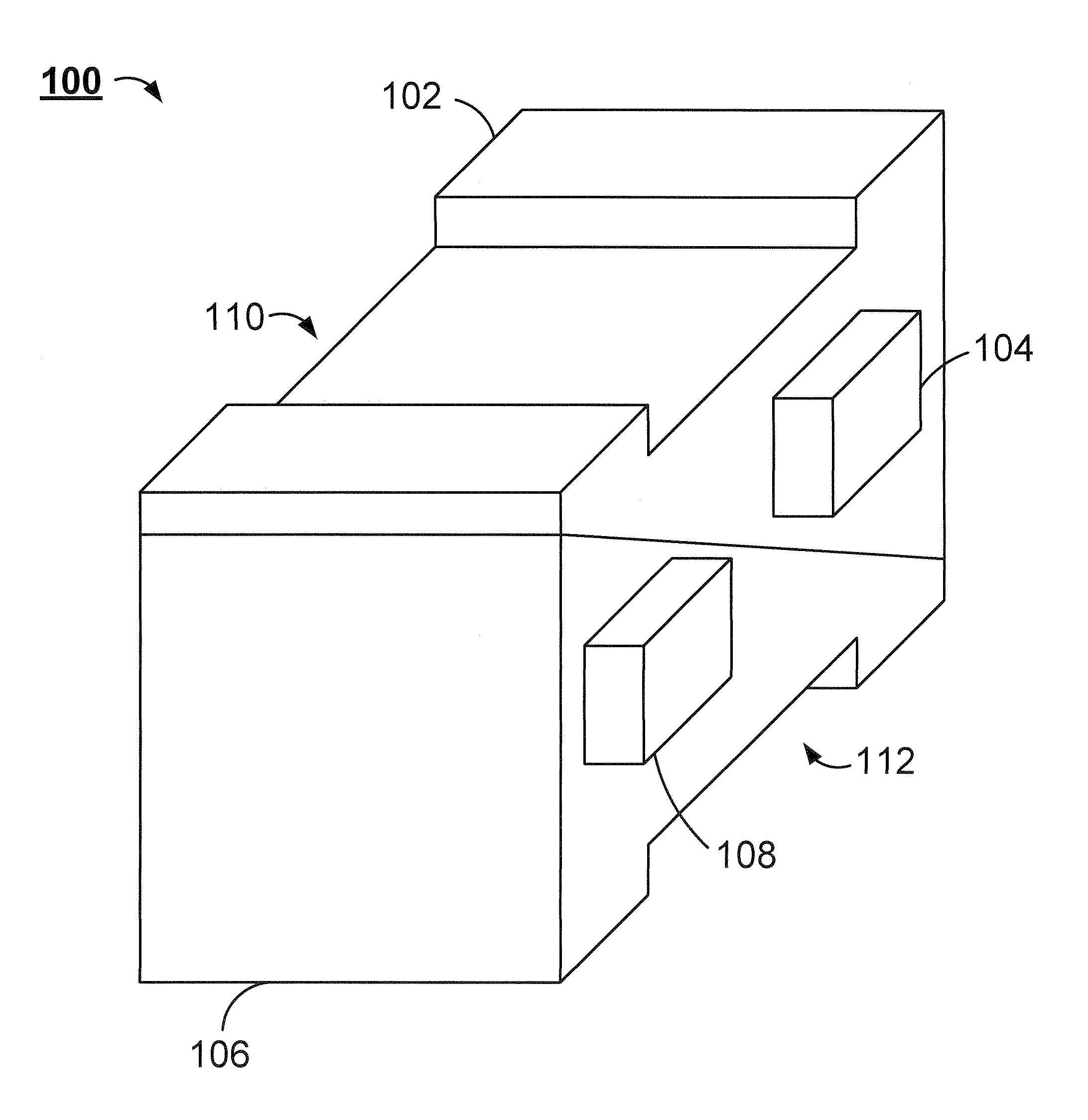
[0018]Preferred embodiments of the present invention are generally directed to a dental appliance configured to provide treatment of mandibular disharmonies, such as Class II malocclusions and rearward divergent mandibles.

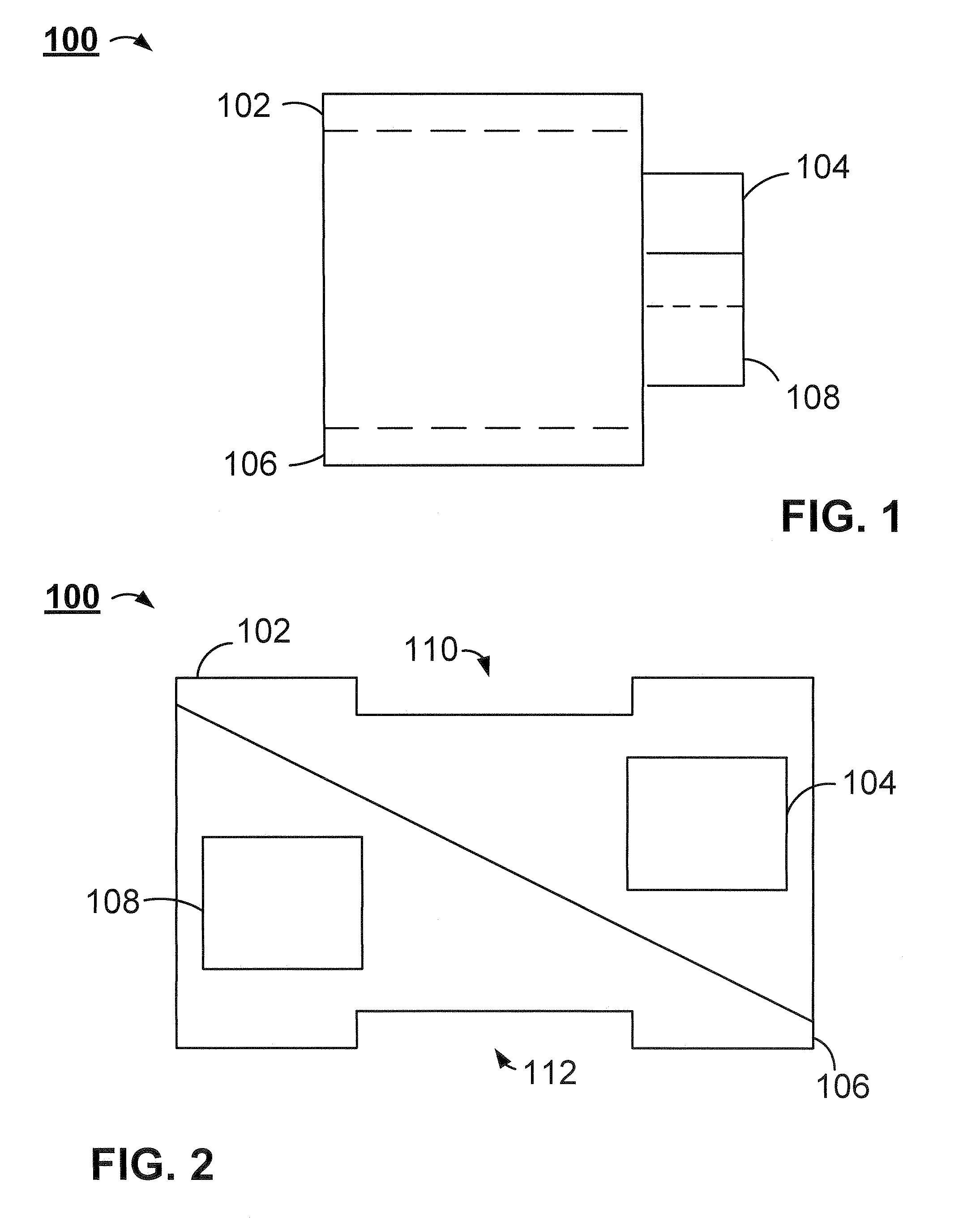
[0019]FIG. 1 shows a front view of the orthodontic appliance 100 (also referred to herein as dental appliance 100) in a preferred embodiment. The dental appliance 100 preferably includes a first member 102 with a main body portion to which a first extraction feature 104 laterally extends. A second member 106 is preferably shown in close proximity to the first member 102. In a preferred embodiment, the second member 106 has a main body portion to which a laterally extending second extraction feature 108.

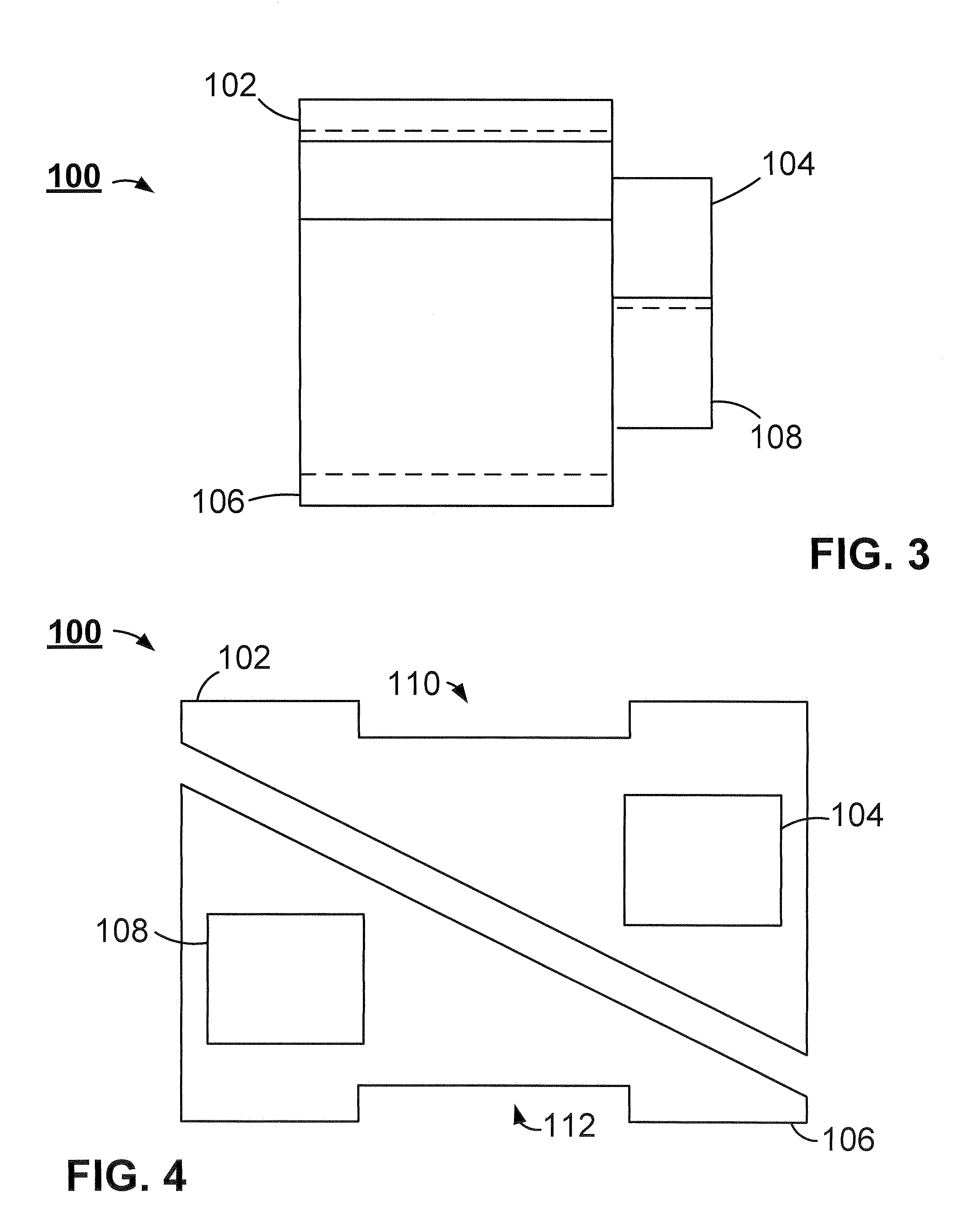
[0020]FIG. 2 displays a side view of the dental appliance 100 in a preferred embodiment. The dental appliance 100 includes a first member 102 and a second member 106 in close proximity. Preferably, the first and second members 102 and 106 can be a variety of sizes to...


PUM


Abstract

A dental appliance that includes at least a first member presenting a first sloped surface and configured for attachment to a first tooth of a patient. Preferably, the first member interacts with a second member presenting a second sloped surface and configured for attachment to a second tooth of the patient. The preferred embodiment includes the interaction between the first and second member's sloped surfaces re-align the patient's jaw to correct mandibular disharmonies. In the preferred embodiment, each of the first and second members includes a laterally extending extraction feature to facilitate separation of the first and second members from the patient's teeth.

Description

FIELD OF THE INVENTION[0001]The present invention relates generally to the field of orthodontic equipment and treatments, but not by way of limitation, to the correction of mandibular disharmonies.BACKGROUND OF THE INVENTION[0002]The ability to safely and efficiently correct dental disharmonies such as malocclusion has been a continued goal in the practice of orthodontic medicine.[0003]Historically, dental disharmonies have been treated with a variety of techniques and devices. Disharmonies such as class II malocclusion have been corrected with complex apparatus that focus force on the mandible to gradually adjust its position in the tempromandibular joint. Likewise, corrective techniques have required continual supervision by a professional to ensure proper adjustment of the mandible. The lack of an efficient appliance to correct dental disharmonies results from the complexity of installation, use, and removal of the corrective appliance. With numerous pieces and precise locations ...

Claims


Application Information

Patent Timeline
IPC IPC(8): A61C3/00
CPCA61C7/023A61C7/36A61F5/566
Inventor PLOWMAN, PAUL E.
Owner PLOWMAN PAUL E
Why Eureka
Eureka Blog
Learn More