High-speed closing switch in power distributor

a technology of high-speed closing switch and power distributor, which is applied in the direction of air-break switch, high-tension/heavy-dress switch, snap-action arrangement, etc., can solve the problems of affecting the user, breaking insulation, and internal devices such as various measurement equipment, and achieve the effect of quick extinguishing an ar

Active Publication Date: 2012-09-04
LG IND SYST CO LTD
View PDF21 Cites 8 Cited by
  • Summary
  • Abstract
  • Description
  • Claims
  • Application Information

AI Technical Summary

Benefits of technology

[0009]Therefore, in order to address the above matters, the various features described herein have been conceived. One aspect of the exemplary embodiments is to provide a high speed closing switch capable of quickly extinguishing an arc generated in a power distributor.
[0010]Another aspect of the present invention is to provide a means for effectively controlling a final position of a moving unit of a switch when the moving unit moves at a high speed.
[0012]With the configuration of the damping hole formed at the receiving recess, when the moving contact point member approaches the final position, a damping force is applied to the moving contact point member, to thus stably and accurately control the final position.

Problems solved by technology

When an arc is generated within a power distributor circuit, an internal device such as various measurement equipments or the like may be damaged due to high temperature and high pressure of the arc, and according to circumstances, insulation is broken to do damage to the user who comes in contact therewith.
When an arc is generated in the power distributor, a trip speed of the breaker is not sufficiently faster than the arc speed to cut off the accident current, so the breaker is not effective.
However, when an arc is generated, it reaches its maximum temperature and pressure very quickly, so the related art method cannot effectively cope with the arc speed.
However, because the moving unit of the breaking device moves at a high speed, it is difficult to reduce the final speed, and thus, it is difficult to control the final position of the moving unit.

Method used


Image

  • High-speed closing switch in power distributor
  • High-speed closing switch in power distributor
  • High-speed closing switch in power distributor

Examples


Embodiment Construction

[0032]A high speed closing switch of a power distributor according to exemplary embodiments of the present invention will now be described with reference to the accompanying drawings.

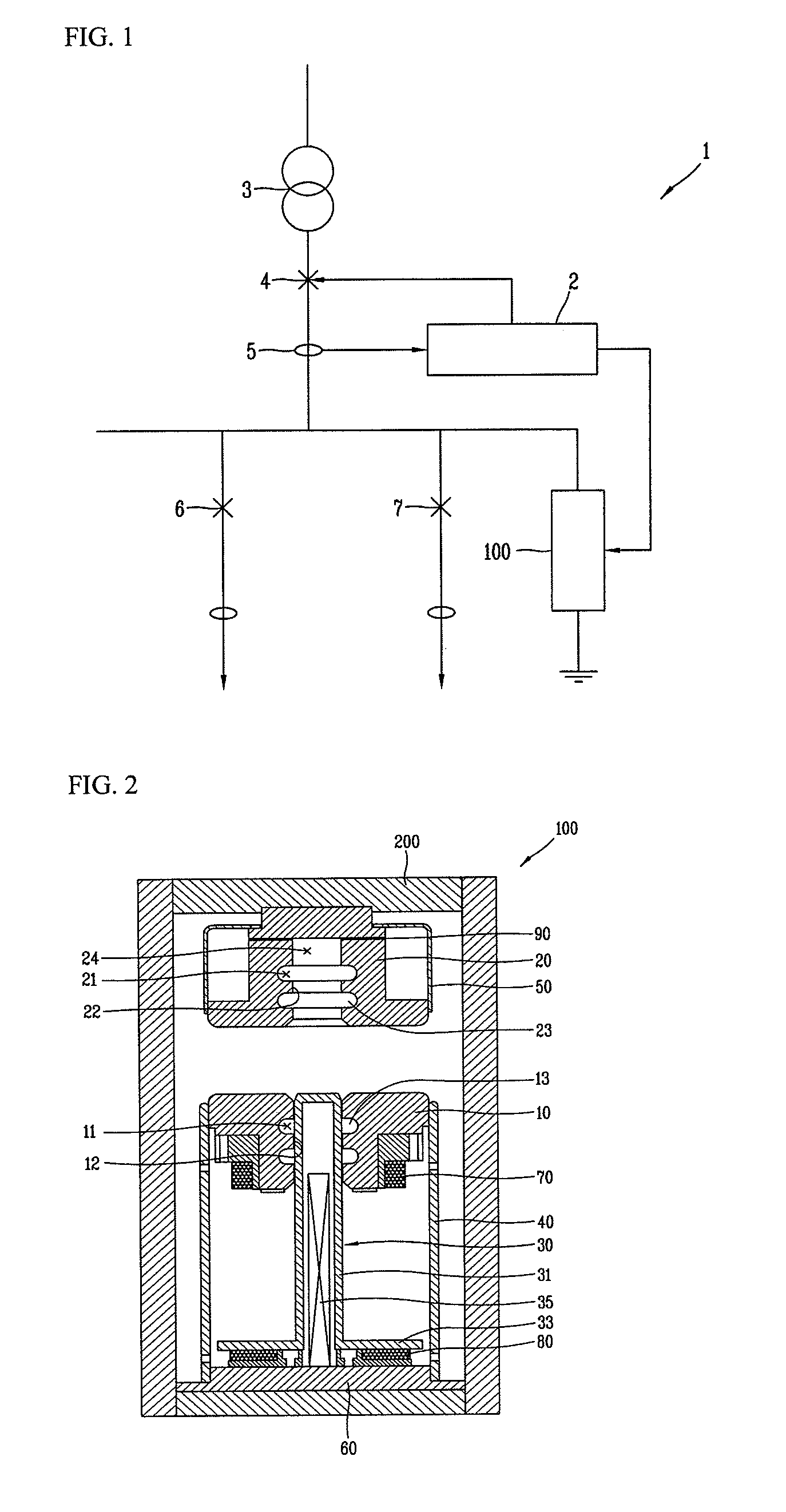
[0033]FIG. 1 is an overall outline view showing a power distributor according to an embodiment of the present invention.

[0034]A power distributor 1 according to an embodiment of the present invention includes an arc-extinguishing system 2, a transformer 3, a main breaker 4, a current sensor 5, a first breaker 6, a second breaker 7, and a high speed closing switch 100.

[0035]In order to deal with an arc generated in the power distributor, when an arc generated within a control system (not shown) of the power distributor 1 is detected, a trip signal is transmitted to the main breaker 4 and, at the same time, the dedicated high speed closing switch 100 is operated. Then, the high speed closing switch 100 detours an arc accident current toward a ground to thereby minimize damage that may be generated due to ...


PUM


Abstract

A high speed closing switch in a power distributor includes: a case forming an external appearance; a first electrode provided within the case and including a through hole; a second electrode having a receiving recess facing the through hole; a moving contact point member having a cylindrical portion received in the through hole so as to be put into the receiving recess and a flange portion formed at one end of the cylindrical portion; and a closing coil wound on a base of the case, wherein a damping hole is formed at receiving recess of the second electrode. When the moving contact point member put into the receiving recess approaches its final position, a damping force is applied to the moving contact point member to stably and accurately control the final position.

Description

BACKGROUND OF THE INVENTION[0001]1. Field of the Invention[0002]The present invention relate to a breaker switch introduced at a high speed within a power distributor and, more particularly, to a high-speed closing switch capable of minimizing damage possibly resulting from an arc accident of a power distributor by inputting high voltage power to a ground at a high speed to detour an accident current immediately when the arc accident occurs at the power distributor.[0003]2. Description of the Related Art[0004]In general, a power distributor is a facility that converts power of an is especially high voltage into a low voltage and distributing the same to provide power required by a load facility installed at each consumer, and in general, the power distributor includes a switch, a lightning arrester, a transformer, a breaker and various other measurement equipments.[0005]The breaker provided in the power distributor refers to a device that breaks current when a line is switched on or...

Claims


Application Information

Patent Timeline
Patent Type & Authority Patents(United States)
IPC IPC(8): H01H33/70
CPCH01H79/00H01H33/285H01H33/20H01H33/42
Inventor JEONG, YOUNG WOOLEE, HYUN WOOKJEONG, HAE EUNSIN, YANG SEOPKIM, YOUNG KEUN
Owner LG IND SYST CO LTD
Why Eureka
Try Eureka