
Method and device for determining ultrasonic detecting cycle

a technology of ultrasonic detection and cycle, applied in the direction of instruments, heat measurement, specific gravity measurement, etc., can solve the problems of erroneous discrimination inability of ultrasonic sensing devices to actually discriminate whether foreign objects enter the sensing range of ultrasonic sensing devices, so as to avoid er

Inactive Publication Date: 2012-09-04
LITE ON TECH CORP
View PDF3 Cites 0 Cited by
  • Summary
  • Abstract
  • Description
  • Claims
  • Application Information

AI Technical Summary

Benefits of technology

[0012]The present invention provides a method and a device for determining an ultrasonic detecting cycle in order to avoid erroneous discrimination due to the multiple reflection effect.

Problems solved by technology

As known, in a case that the undesired noise is received, erroneous discrimination of the ultrasonic sensing device occurs.
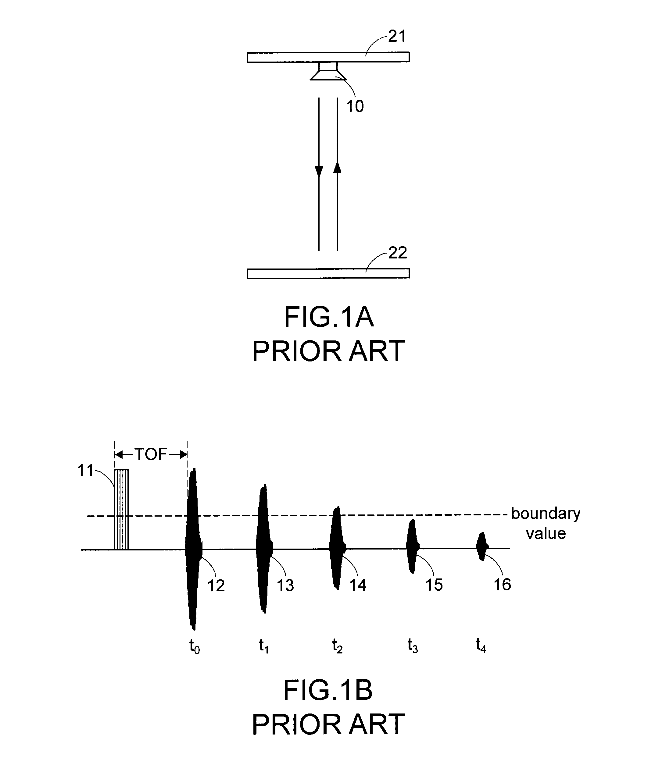
However, if a multiple reflection effect of the sensing wave occurs, the ultrasonic sensing device fails to actually discriminate whether any foreign object enters the sensing range of the ultrasonic sensing device.
Under this circumstance, the ultrasonic sensing device may erroneously discriminate that a foreign object enters the sensing range.

Method used


Image

  • Method and device for determining ultrasonic detecting cycle
  • Method and device for determining ultrasonic detecting cycle
  • Method and device for determining ultrasonic detecting cycle

Examples


first embodiment

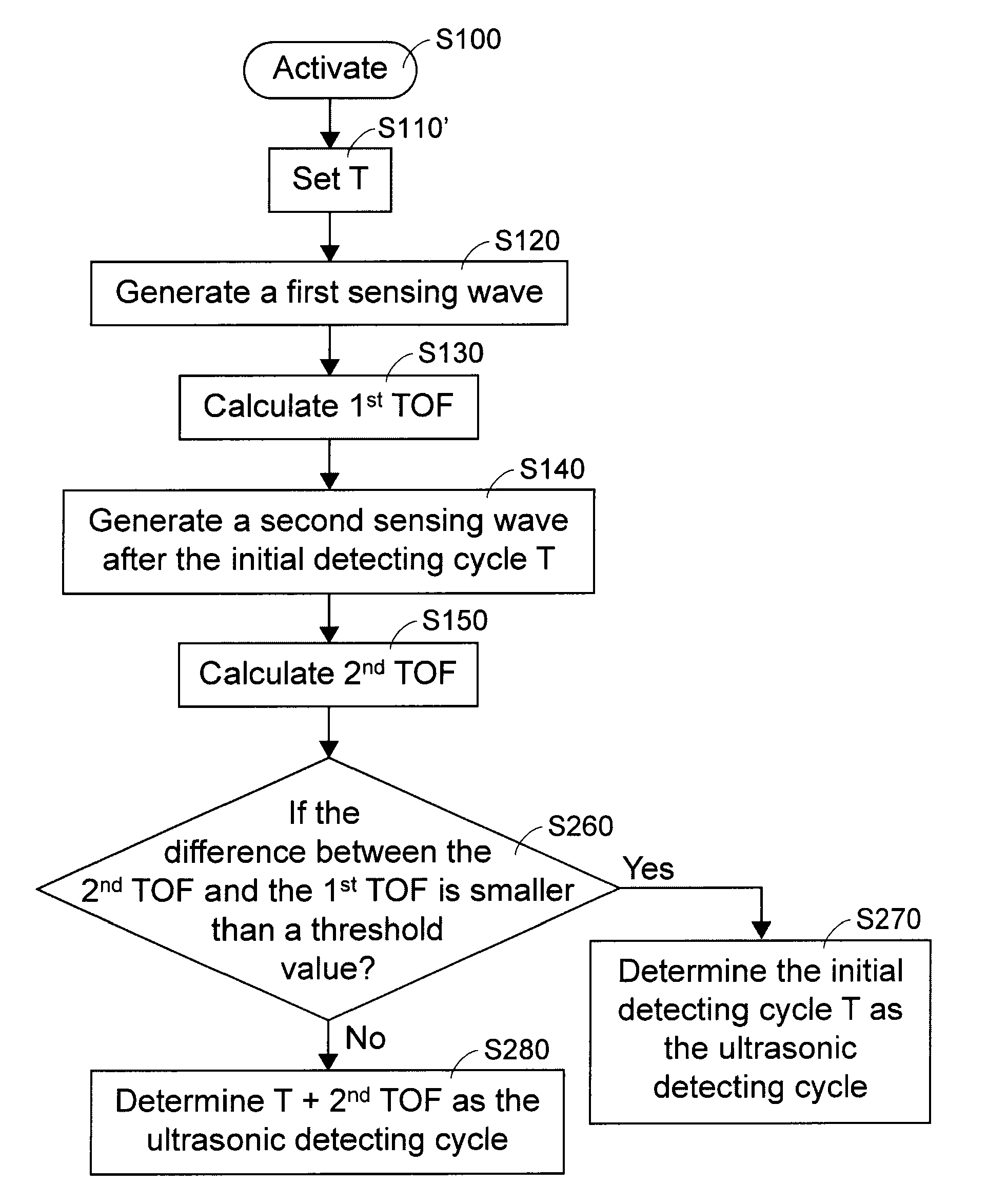
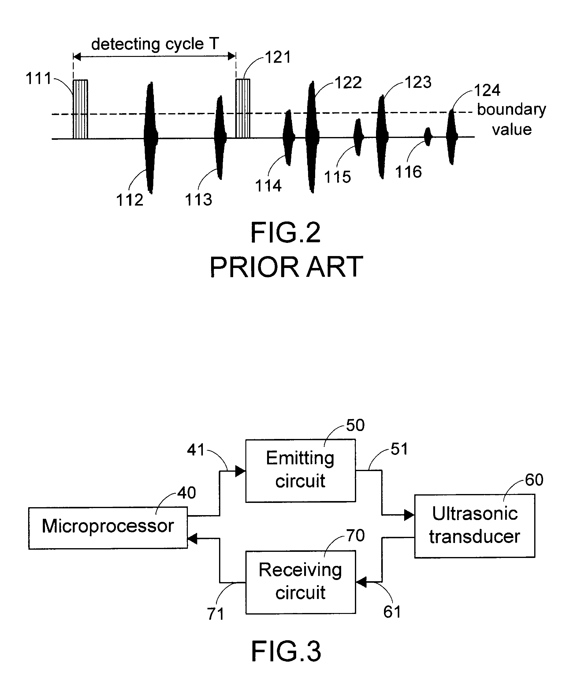
[0027]FIG. 4A is a flowchart illustrating a method for determining an ultrasonic detecting cycle according to the present invention. After the ultrasonic sensing device is activated (Step S100), the microprocessor 40 sets an initial detecting cycle T, a time increment ΔT and a variable integer n, where n=0 (Step S110). Next, the ultrasonic sensing device generates a first sensing wave (Step S120). When the first sensing wave hits the reference object, an echo signal is reflected by reference object and then received by the ultrasonic sensing device. Next, according to the effective echo signal first received after the first sensing wave is generated, the microprocessor 40 calculates a first time-of-flight value (1st TOF) (Step S130). After the initial detecting cycle T, the microprocessor 40 generates an emitting signal and thus the ultrasonic sensing device generates a second sensing wave (Step S140). Similarly, when the second sensing wave hits the reference object, an echo signal...

second embodiment

[0037]FIG. 5A is a flowchart illustrating a method for determining an ultrasonic detecting cycle according to the present invention. After the ultrasonic sensing device is activated (Step S100), the microprocessor 40 sets an initial detecting cycle T (Step S110′). Next, the ultrasonic sensing device generates a first sensing wave (Step S120). According to the effective echo signal first received after the first sensing wave is generated, the microprocessor 40 calculates a first time-of-flight (1st TOF) value (Step S130). After the initial detecting cycle T, the ultrasonic sensing device generates a second sensing wave (Step S140). According to the effective echo signal first received after the second sensing wave is generated, the microprocessor 40 calculates a second time-of-flight (2nd TOF) value (Step S150).

[0038]Next, the microprocessor 40 will compare whether the difference between the second time-of-flight value and the first time-of-flight value is smaller than a threshold va...


PUM


Abstract

A method for determining an ultrasonic detecting cycle is provided. Firstly, an initial detecting cycle T is set. Then, a first sensing wave is generated. Then, a first time-of-flight value is calculated corresponding to the first sensing wave. After the first sensing wave has been generated for the initial detecting cycle T, a second sensing wave is generated. Then, a second time-of-flight value is calculated corresponding to the second sensing wave. Afterwards, the second time-of-flight value is compared with the first time-of-flight value. If a difference between the second time-of-flight value and the first time-of-flight value is smaller than a threshold value, the initial detecting cycle T is determined as the ultrasonic detecting cycle.

Description

FIELD OF THE INVENTION[0001]The present invention relates to a method and a device for detecting ultrasonic wave, and more particularly to a method and a device for determining an ultrasonic detecting cycle.BACKGROUND OF THE INVENTION[0002]An ultrasonic sensing device is widely used for measuring a relative distance or detecting whether an object is within the sensing range of the ultrasonic sensing device. According to the measuring or detecting result, further actions will be performed.[0003]Generally, when the ultrasonic sensing device is activated, a sensing wave is generated to detect whether any object is within the sensing range of the ultrasonic sensing device. In a case that an object enters the sensing range of the ultrasonic sensing device, the sensing wave is reflected by the object and the reflected sensing wave (also referred as an echo signal) is returned back to the ultrasonic sensing device. When the echo signal is received, the ultrasonic sensing device will calcul...

Claims


Application Information

Patent Timeline
Patent Type & Authority Patents(United States)
IPC IPC(8): G01S15/00
CPCG01S7/527G01S15/101
Inventor YI-MIN, LIN
Owner LITE ON TECH CORP
Learn More