Bandwidth control device

a control device and bandwidth technology, applied in the direction of gas laser construction details, laser details, active medium materials, etc., can solve the problems of unsatisfactory short-term and/or long-term wavefront transients

Active Publication Date: 2012-09-04
CYMER INC
View PDF17 Cites 7 Cited by
  • Summary
  • Abstract
  • Description
  • Claims
  • Application Information

AI Technical Summary

Problems solved by technology

To varying degrees, however, the possible ways to apply the desired compressive and tensile forces have certain drawbacks to being able to actively control the grating shape for wavefront control, e.g., the addition of heat, and thus thermal effects, into the LNM and surrounding laser system modules or module components that can cause undesirable short term and / or long term wavefront transients.

Method used


Image

  • Bandwidth control device
  • Bandwidth control device
  • Bandwidth control device

Examples


Embodiment Construction

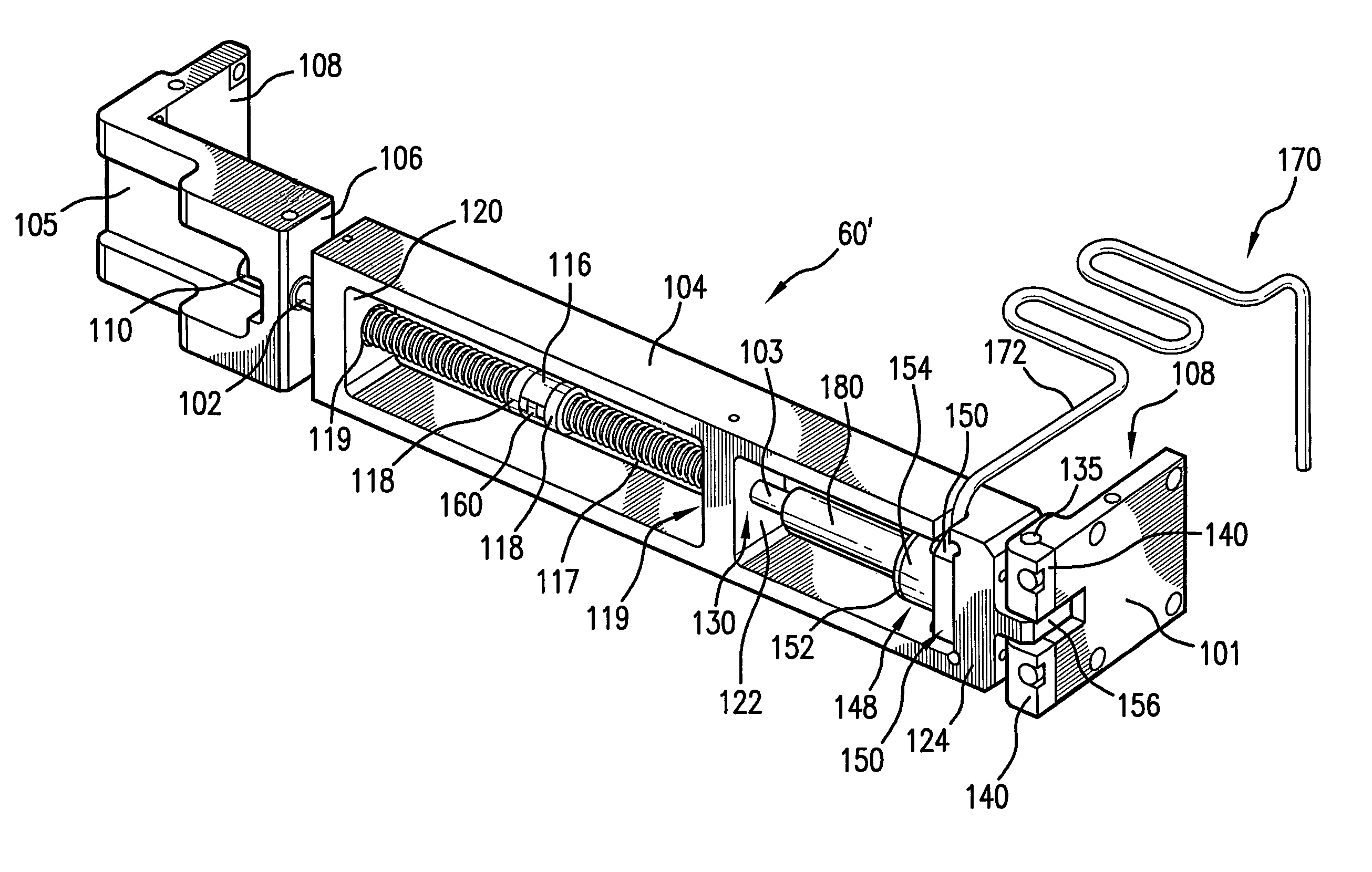
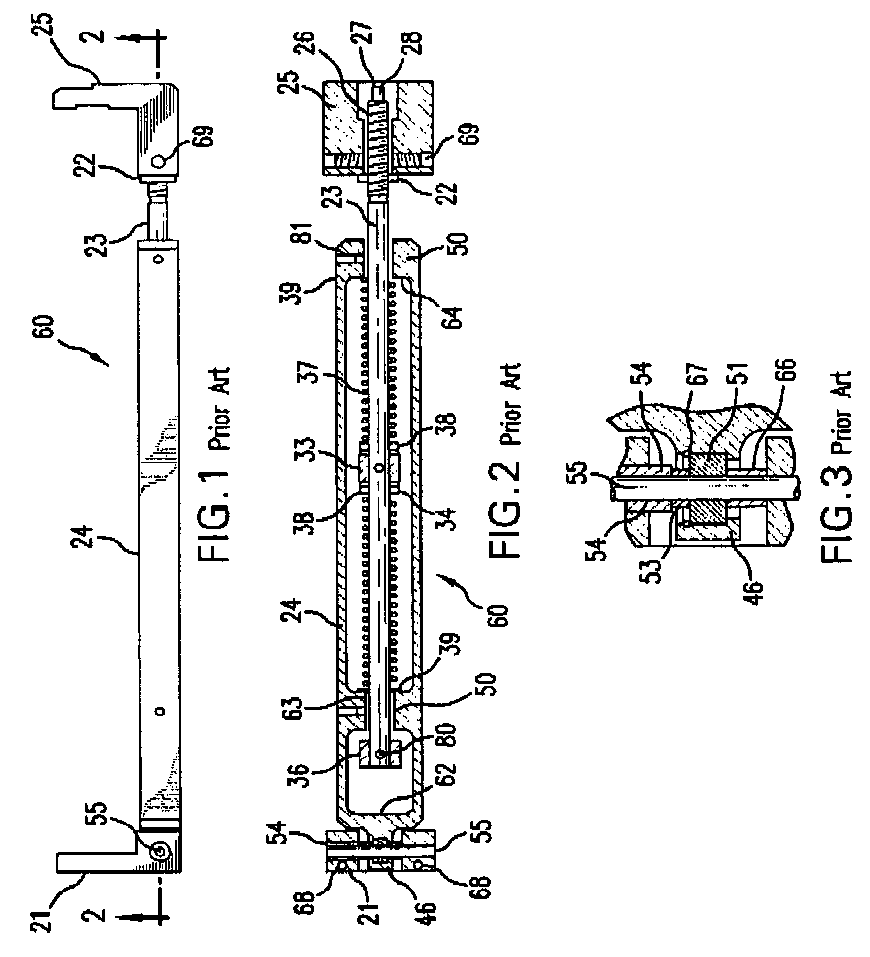
[0025]Applicants' employer has determined that there is a theoretical amount of bending of the LNM grating caused by turning the compression spring shaft on the BCD in a compressive direction or a tensile direction, called for convenience counter clockwise (“CCW”) and clockwise (“CW”). Calculations have been made of beam wavefront change introduced by a given amount of grating bending. Wavefront measurements have been made showing changes in diffracted wavefront with BCD setting. Manufacturing data has been taken in an effort to correlation between grating power and the BCD setting, e.g., turns CW or CCW, e.g., from a neutral, non-bending position. Experimental data and theoretical calculations have been done to showing linewidth as a function of BCD setting.

[0026]With regard to the theoretical amount of bending caused by turning the BCD, calculations show that with regard, e.g., to the mechanical properties of the 35×35×250 mm ULE substrate, somewhat typical for the substrate for a...


PUM


Abstract

A method and apparatus is disclosed for operating a laser output light beam pulse line narrowing mechanism that may comprise a nominal center wavelength and bandwidth selection optic; a static wavefront compensation mechanism shaping the curvature of the selection optic; an active wavefront compensation mechanism shaping the curvature of the selection optic and operating independently of the static wavefront compensation mechanism. The method and apparatus may comprise the nominal center wavelength and bandwidth selection optic comprises a grating; the static wavefront compensation mechanism applies a pre-selected bending moment to the grating; the active wavefront compensation mechanism applies a separate selected bending moment to the grating responsive to the control of a bending moment controller based on bandwidth feedback from a bandwidth monitor monitoring the bandwidth of the laser output light beam pulses. The active wavefront compensation mechanism may comprise a pneumatic drive mechanism.

Description

FIELD OF THE INVENTION[0001]The present invention is related to active bandwidth control in high power, high repetition rate, very line narrowed excimer and molecular fluorine gas discharge laser systems, e.g., for use in integrated circuit manufacturing photolithography as a DUV light source, e.g., in KrF at around 248 nm nominal center wavelength and ArF at around 193 nm nominal center wavelength laser light sources.CROSS-REFERENCE TO RELATED APPLICATIONS[0002]The present application is related to U.S. Pat. No. 5,095,492, entitled SPECTRAL NARROWING TECHNIQUE, issued to Sandstrom on Mar. 10, 1992; and this application is related to U.S. Pat. No. 5,970,082, entitled VERY NARROW BAND LASER, issued to Ershov on Oct. 19, 1999; and this application is also related to U.S. Pat. No. 6,094,448, entitled GRATING ASSEMBLY WITH BI-DIRECTIONAL BANDWIDTH CONTROL, issued to Fomenkov et al. on Jul. 25, 2000; and this application is also related to U.S. Pat. No. 6,192,064, entitled NARROW BAND LA...

Claims


Application Information

Patent Timeline
Patent Type & Authority Patents(United States)
IPC IPC(8): H01S3/136
CPCH01S3/225H01S3/03H01S3/034H01S3/08009H01S3/137H01S3/2256
Inventor FOMENKOV, IGOR V.PARTLO, WILLIAM N.REILEY, DANIEL J.HOWEY, JAMES K.AGUILAR, STANLEY C.
Owner CYMER INC
Why Eureka
Try Eureka